CNC machined shafts need more than the correct outside diameter. A shaft may fit its mating hole yet fail to locate a component correctly if a shoulder is in the wrong position, a cross hole is misaligned, or a specified surface runs out relative to the drawing datum. The drawing should identify which diameters provide the fit, which faces locate the assembly, and which features require geometric control.
At SAMSHION, we machine shaft components in aluminum, stainless steel and tool steel. Our usual route starts with turning the outside diameters and steps, followed by milling flats and slots and machining cross holes. Heat treatment and grinding for tool steel depend on the drawing requirements. This guide explains how those operations connect to the features buyers need to specify and the checks needed before acceptance.
Start with the material and final condition
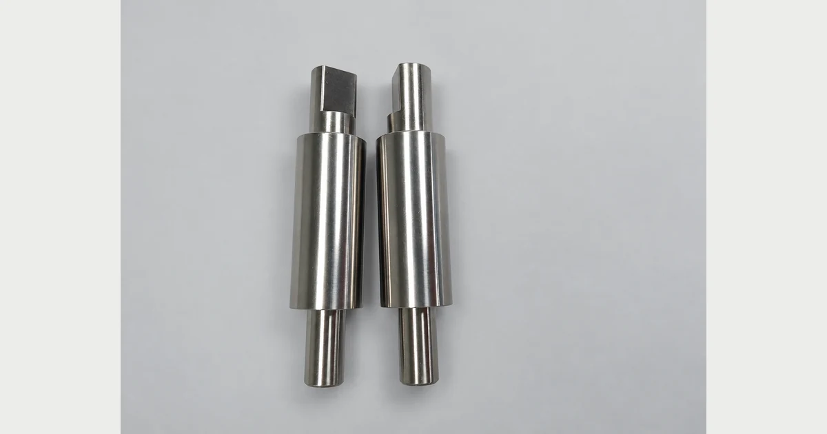
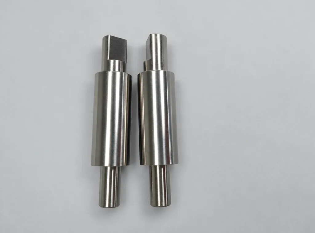
Specify the material grade and supply condition rather than identifying a part only as an aluminum shaft or a steel shaft. The manufacturing plan also needs any required final hardness and surface treatment. A photograph can show a stepped diameter or a flat, but it cannot establish the alloy, hardness or coating.
For tool steel shafts, confirm whether heat treatment is required and which surfaces must be finished afterward. If grinding is needed to meet a drawing requirement, its position in the route and the stock allowance must be planned before machining. Grinding should not be added automatically to every shaft, and a drawing that specifies a hardened condition should not be treated as an ordinary soft-material job.
If a coating or other finishing process affects a fitted diameter, state whether the size requirement applies before or after that process. The final acceptance condition must be clear when the quotation and inspection plan are prepared.
Plan shaft turning and milling around the same references
Turning is suited to the cylindrical diameters, steps and end faces of a shaft. Milling and hole making add features such as flats, slots, end pockets and transverse holes. Our turning and milling comparison explains the broader differences between these operations.
For stepped shaft machining, the transition between operations needs attention. A milled feature may have to be located from a particular turned diameter and shoulder rather than from whichever surface is easiest to grip. The process plan should preserve those relationships when the part moves to another setup.
Where possible, plan related cylindrical features together and identify how the references will be recovered for subsequent operations. This does not mean that every shaft can be completed in one clamping. Part length, access and the drawing requirements determine the route. See our guide to datum transfer across multiple setups for the setup issues involved.
Longer shaft components also need a review of unsupported length and access to the end features. Support and gripping arrangements should suit the actual geometry without damaging or distorting a functional surface. The support selected for machining is a process decision; it is not automatically the datum arrangement required for final inspection.
Define fitting diameters and shoulder locations
Fitting outside diameters
Mark each functional diameter and give its size limits or fit designation. A sliding fit and an interference fit serve different purposes, so a single general tolerance may not express the assembly requirement. The mating component and intended assembly condition should guide the specification.
Identify the axial length over which each diameter must meet the requirement. A short locating section and a long fitted section may share a nominal diameter while needing different attention during manufacture and inspection. Also define any relevant surface roughness and geometry requirements separately from size.
A micrometer is useful for outside-diameter checks, but a few diameter readings do not establish every aspect of the surface form or its relationship to another feature. Measurement locations and any additional geometric evaluation should follow the drawing and inspection plan.
Step lengths and axial location
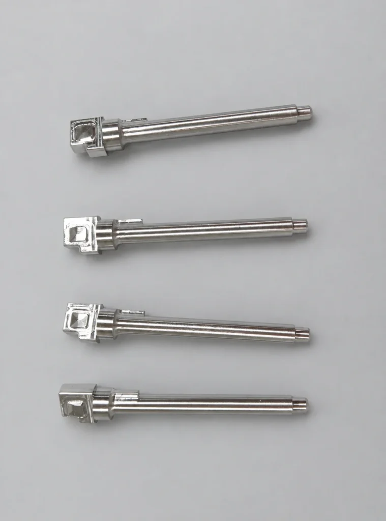
A shoulder often locates a mating part along the shaft. Its distance from the specified reference face can therefore matter more than a dimension measured from the opposite end. Define the functional axial dimensions directly and avoid leaving the supplier to infer which shoulder establishes the assembly position.
Review corner radii, chamfers and reliefs where a mating part seats against a shoulder. A diameter and length can both meet their limits while an unintended corner interference prevents full seating. Any shoulder-face orientation requirement should also be stated explicitly; a length tolerance alone does not specify that orientation.
Locate flats, slots and cross holes from functional datums
A flat, slot or cross hole needs both a size requirement and a location requirement. Slot width does not establish where the slot sits along the shaft. Cross-hole diameter does not establish its distance from a shoulder or its angular relationship to a flat.
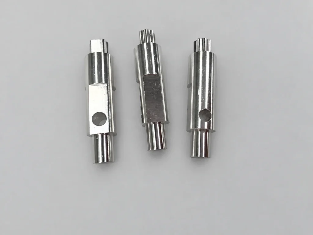
For a transverse hole, define its diameter, whether it passes through the part, and the required location relative to the relevant shaft axis and face. If several features must align around the shaft, show their angular relationship. For a flat, include its depth or the resulting dimension across the part as appropriate to the design.
Open and closed slots also require different access considerations. State the depth, end geometry and permitted corner radii so the machining method can be reviewed before production. Where process selection is uncertain, our keyways and slots guide discusses milling and alternative methods. An ordinary slot should not be described as a precision keyway unless that is its actual function.
For positional tolerances, include the datum references and the drawing standard. The supplier needs these to distinguish a coordinate dimension from a geometric position requirement. Our GD&T guide for CNC quotations covers what to include at enquiry stage.
Specify runout relative to the required datum axis
Runout describes surface variation as a part rotates about a specified datum axis. It is a separate requirement from outside-diameter size. Two diameters can each meet their size limits while a surface still exceeds its runout limit relative to the required axis. KEYENCE explains this datum relationship.
Circular runout evaluates individual circular sections. Total runout evaluates the specified surface as a whole, so a circular-runout check at one section cannot establish total-runout compliance. The drawing should identify the controlled surface, datum reference and required control. Radial and axial runout are also different directions of evaluation. Mitutoyo illustrates these distinctions.
At SAMSHION, we use a runout tester for shaft runout checks. The fixture must establish the required reference appropriately. A convenient support arrangement does not, by itself, prove that the drawing datum has been represented. The inspection plan should specify the support or locating method, measurement direction and evaluation locations.
Runout should not be renamed concentricity or treated as proof of dynamic balance. Those are different requirements. If the drawing uses an ambiguous note such as “keep both diameters concentric,” clarify the intended geometric control before manufacturing.
Match shaft inspection to the feature being accepted
The equipment we use for shaft inspection includes micrometers, a coordinate measuring machine or CMM, a height gauge and a runout tester. Select the method for the feature, tolerance and available access rather than assuming that one instrument answers every inspection question.
The following table is an inspection-planning guide. It does not report measured results for the photographed parts.
The exact setup depends on the part. A height-gauge check needs a suitable reference and stable positioning. A CMM evaluation needs an alignment based on the required datums and a probing strategy that can reach the relevant geometry. A slot that is too narrow for the available probe needs another suitable method agreed for that requirement.
Record the drawing revision and identify the measured features clearly when a dimensional report is required. For runout, a useful record also identifies the reference and evaluated surface. More information about inspection equipment and reporting is available in our CNC machining inspection guide.
Review surface condition without losing the size requirement
Fitted diameters and locating shoulders should be protected during handling, subsequent operations and packing. Surface damage in these areas can interfere with seating even when an earlier dimensional check was satisfactory. Cosmetic requirements should identify the relevant surfaces and the acceptable condition rather than relying only on a general instruction to avoid marks.
Where deburring or local rework is needed, preserve the functional edges and dimensions. Removing a mark by uncontrolled polishing can change a fitted diameter or round a locating shoulder. Any proposed rework that could affect a drawing requirement needs review before it is carried out.
For tool steel shafts that require heat treatment and further finishing, the hardened tool steel machining guide explains how CNC machining, grinding and other processes can be combined. The actual route remains dependent on the specified material and final requirements.
Information to include with a shaft machining enquiry
Send the 3D model together with a controlled drawing. The drawing should communicate the shaft machining tolerances and acceptance requirements that cannot be inferred from the model alone.
- Material grade and condition, including any required heat treatment or surface treatment.
- Functional outside diameters and their fitted lengths.
- Step lengths, locating faces and relevant shoulder details.
- Runout callouts, datum references and the applicable drawing standard.
- Flats, slots and cross holes with their size and location requirements.
- Surface roughness, cosmetic requirements, quantity and required inspection documentation.
If an assembly relationship is difficult to explain on the part drawing, provide the relevant mating-part information or an assembly view. This helps the supplier understand which features establish the fit without changing the customer’s design requirements.
Common questions about CNC machined shafts
Can shafts include milled features as well as turned diameters?
Yes. We normally turn the outside diameters and steps first, then machine flats, slots and cross holes. Their relationships to the turned features must remain defined through the later setups.
Does every tool steel shaft need heat treatment and grinding?
No. We determine those operations from the drawing requirements. Material condition, hardness and the final size and finish requirements need to be considered when planning the route.
Is an acceptable outside diameter enough to prove acceptable runout?
No. Outside-diameter size and runout answer different inspection questions. The runout requirement must be checked relative to its specified datum axis.
Discuss your shaft drawing with SAMSHION
Send us the shaft model, drawing and quantity, and identify the fitting diameters, locating shoulders and runout requirements. We can review the turning and milling route, any drawing-dependent heat treatment or grinding, and the inspection requirements before quotation.