Robotic joint accuracy depends on more than the diameter of a bearing bore. H7 bore size, bore position, axis orientation, mounting-face geometry, datum relationships, machining sequence and final inspection must be considered as one functional system. This guide explains how those requirements influence CNC machining robotic arm joints from prototype through repeat production.
Quick answer: An H7 bore controls size within the ISO tolerance system, but it does not by itself control bore position, perpendicularity, cylindricity, alignment with another bore or the condition of a mounting face. Those requirements need separate drawing controls and suitable inspection methods.
Key Takeaways
- H7 is a size tolerance zone whose width depends on the nominal bore diameter.
- A bore can pass a diameter check and still fail assembly because its axis or datum relationship is incorrect.
- The datum scheme should represent how the robotic joint is located and assembled, not only how it is convenient to machine.
- 5-axis machining may reduce setup transfers, but it does not automatically guarantee accuracy or eliminate every second setup.
- Critical bores and related mounting faces may need to be finish-machined together after part flipping or surface treatment.
- First-off inspection, in-process sampling and final inspection provide different forms of control and should not be treated as interchangeable.
Why Robotic Arm Joints Are Sensitive to Small Alignment Errors
A robotic arm joint may combine bearing seats, locating holes, threaded interfaces, motor mounting features and reference faces in one compact component. These features influence bearing installation, shaft alignment, joint rotation, gearbox or motor location and final assembly behavior.
A bearing bore may meet its stated H7 size and the part may still be difficult to assemble. Common causes include an incorrectly located bore axis, insufficient perpendicularity to the mounting face, poor alignment between related bores, inadequate flatness, burrs, coating buildup or datum-transfer error between setups.
For this reason, engineers should review bore size and functional geometry together rather than treating H7 as a complete assembly specification.
What Does an H7 Bearing Bore Control?
H7 is a hole tolerance designation within the ISO limits and fits system. The letter H identifies a hole tolerance zone with zero lower deviation, while grade 7 determines the tolerance width for the relevant nominal size range. The allowable width is therefore not one fixed plus-or-minus value for every diameter.
A controlled drawing should identify the nominal bore diameter, the required tolerance zone, the mating bearing or shaft condition, the functional datum relationships, the surface condition and the inspection state.
For a broader comparison of drilling, reaming and boring, review our precision hole machining and tolerance guide.
Why an H7 Bore Can Pass Inspection but Fail Assembly
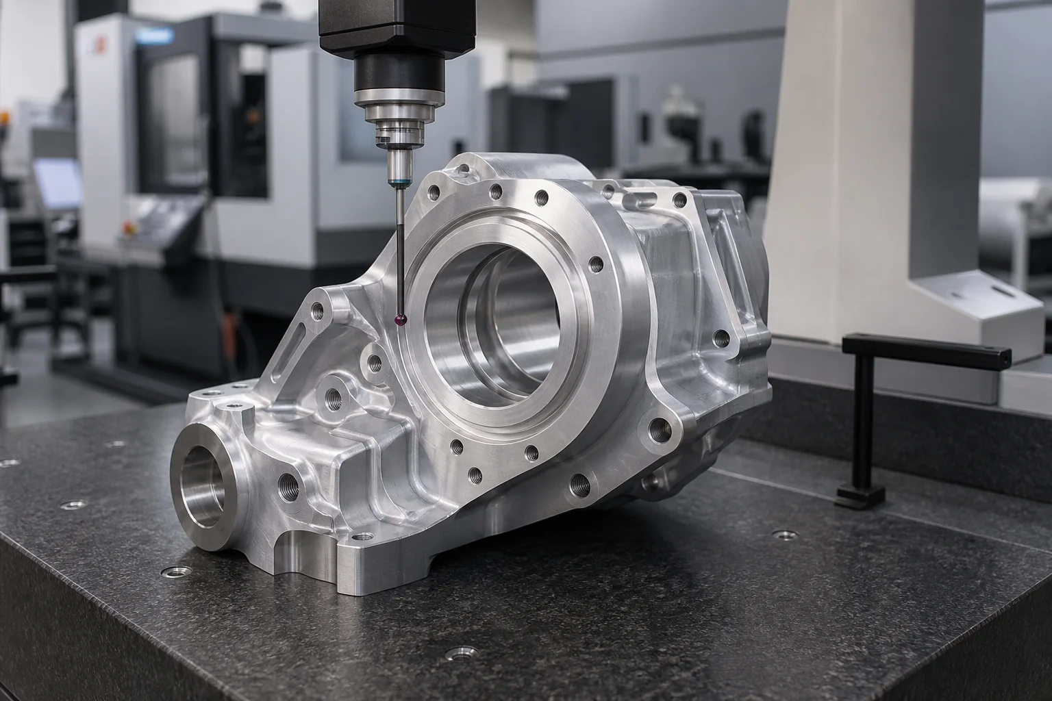
A bore gauge is useful for checking diameter at selected locations and directions, but it cannot prove bore position or perpendicularity. A CMM can evaluate bore axes and datum relationships when the datum construction, measurement strategy, fixturing and uncertainty are appropriate for the requirement.
Is H7 the Correct Choice for Every Robotic Joint?
No. The appropriate fit depends on the bearing specification, nominal diameter, which ring rotates relative to the load, housing and shaft materials, operating temperature, assembly method, service requirements and the bearing manufacturer’s recommendations.
An aluminum housing and a steel bearing respond differently to temperature. Surface treatment can also change the available fit if the bore is coated or later re-machined. A supplier should not select an H7 bore for every joint without the mating-component and functional information.
ISO 2768 Does Not Replace H7 or GD&T
General tolerances such as ISO 2768 can provide defaults for dimensions or geometrical features that are not individually specified. They do not replace an explicitly controlled H7 bore, position tolerance, perpendicularity, parallelism or flatness requirement.
Features that control bearing installation and joint alignment should be identified individually on the controlled drawing. See our manufacturing tolerance guidance for additional context.
Connect the Datum Scheme to the Real Assembly
A machining datum should not be selected only because it is convenient to hold. The datum reference framework should represent how the joint is located and constrained in the final assembly.
For illustration, a design might use a primary mounting face as datum A, the main bearing-bore axis as datum B and a locating hole or side feature as datum C. A second bearing bore or motor interface could then be controlled relative to that framework. This is only an example. The actual datum order must follow the function of the specific assembly.
ISO 5459 provides the principles used to establish datums and datum systems, while ISO 1101 defines the geometrical-tolerancing language used for form, orientation, location and runout controls.
When Does a Robotic Joint Need 5-Axis Machining?
5-axis machining can be valuable when bearing bores, locating holes, mounting faces and complex profiles must be reached from several directions. Fewer manual repositioning steps may reduce datum-transfer risk and improve access with shorter tools.
However, a 5-axis machine does not guarantee that a component can be completed in one setup. Fixtures, stock access, tool-holder clearance, part stiffness and inspection requirements may still require a second controlled setup. Simpler components may be more practical on 3-axis, indexed 3+2, turning or mill-turn equipment.
The route should be selected from the actual geometry and requirements. Review our 5-axis CNC machining services for a comparison of indexed and simultaneous strategies.
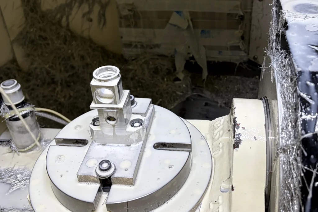
Process Planning for Robotic Joint Components
1. Identify Functional Interfaces
Separate general dimensions from features that directly affect assembly, including bearing bores, locating holes, drive axes, sealing faces, motor interfaces and controlled mounting surfaces.
2. Establish a Stable Datum Route
Roughing, semi-finishing and finishing should preserve a clear relationship between machining and inspection datums. When a part must be flipped, the process should define how the datum is recovered and how transfer error will be verified.
3. Leave Appropriate Finishing Allowance
Depending on geometry and requirements, a precision bore may be completed by boring, reaming, circular interpolation, turning, grinding, honing or a qualified combination. There is no universal method for every H7 bore.
4. Control Stress and Distortion
Open housings, thin walls and components with substantial material removal may move as internal stress is released. Balanced stock removal, staged machining and a suitable finishing sequence can help protect the final bore-to-face relationship.
Finish Machining After the Part Is Flipped
Some critical features cannot be reached from one orientation. In these cases, the part is flipped and re-located before bearing bores, locating holes or mounting faces are finished.
The process may use previously machined holes, reference faces or a dedicated fixture to recover the datum structure. If two bores must share a controlled relationship, checking each diameter separately is not sufficient. Their axes must also be evaluated against the drawing requirements.
Finish Machining After Surface Treatment
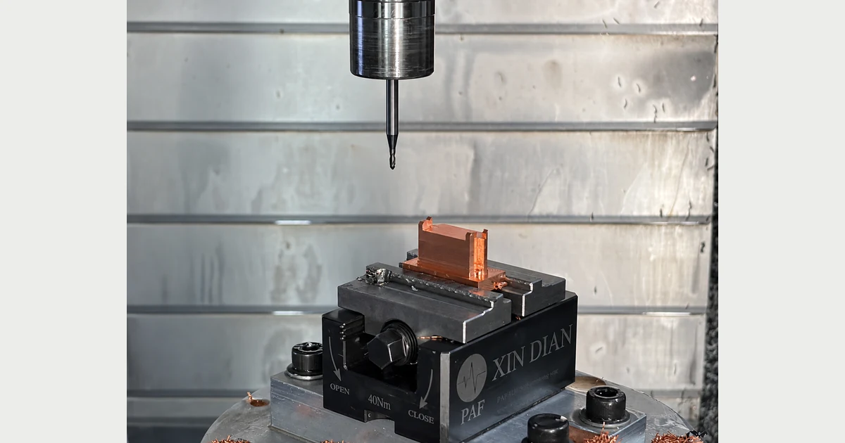
Some robotic joints require H7 bores, locating holes or mounting faces to be re-machined after anodizing or another surface treatment. The objective may be to restore final fit dimensions and to control the relationship between a precision bore and a functional mounting face.
When a bore axis must be perpendicular to a mounting face, the bore and related face are finish-machined in the same controlled setup when geometry permits. If they cannot be completed together, datum recovery and final verification become essential.
The drawing or order should confirm which areas are masked, which features are re-machined, whether exposed base material is acceptable and whether acceptance applies before or after treatment. Final measurements must represent the delivered condition.

Why Bore Gauging and CMM Inspection Must Work Together
The correct method depends on feature geometry, tolerance and report scope. See the CNC machining inspection guide for broader inspection planning.
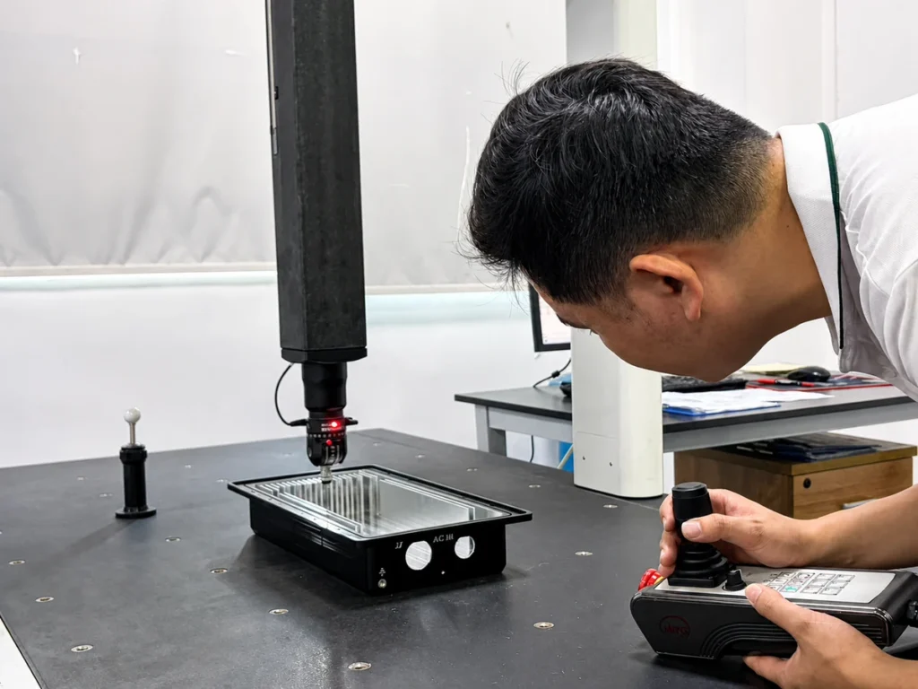
From First-Off Approval to In-Process Sampling
For batch work, production begins with a first-off part rather than an uninterrupted run of the full quantity. The first-off part is inspected against the controlled drawing and order requirements. Production continues only after the first-off result is accepted.
- Confirm the drawing revision, material and inspection requirements.
- Complete machine setup and produce the first-off part.
- Inspect the first-off dimensions and critical characteristics.
- Continue production after the first-off part is accepted.
- Perform in-process sampling according to the approved inspection plan.
- Record results and monitor for tool wear, dimensional drift and setup changes.
- Stop and control the process if a nonconformity is found.
Sampling frequency is selected according to order quantity, feature risk, process stability and customer requirements. One fixed sampling quantity is not suitable for every order.
Quality Documents and CMM Report Scope
SAMSHION provides a full dimensional inspection report and material documentation with each order. Multiple sample parts are measured according to order quantity rather than relying on one fixed sample for every batch.
If a project requires CMM verification of position, perpendicularity, parallelism, bore axes or other GD&T characteristics, the CMM scope and report should be confirmed during quotation. This allows the parties to agree on the datum construction, controlled features, sample quantity and required report format.
A dimensional report provided with an order does not automatically mean that every dimension on every part receives 100 percent inspection. Any feature requiring 100 percent inspection must be identified before production.
Final Inspection Before Shipment
After machining and surface treatment, parts pass through final sampling, appearance review and packaging verification before shipment.
- Verify the final sample dimensions and functional characteristics.
- Check surface-treatment condition, appearance, burrs, sharp edges, dents, scratches and residue.
- Confirm part quantity, drawing revision and order identification.
- Protect precision bores, sealing faces and finished mounting surfaces from contact damage.
- Review packaging condition before release for shipment.
These controls form part of the broader quality assurance process.
Real Manufacturing Example 1: 5-Axis Robotic Arm Prototype
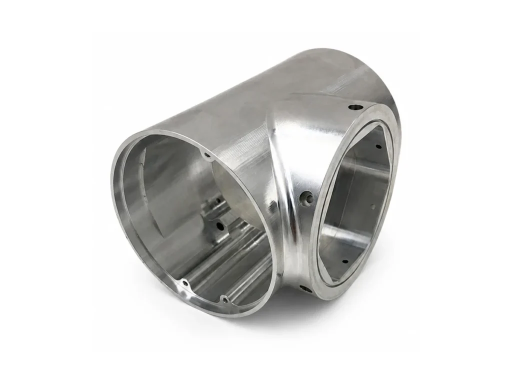
SAMSHION manufactured a single 6061-T6 robotic arm component using 5-axis CNC machining. The controlled features included H7 bearing and locating bores, positional relationships and perpendicularity between the precision bores and functional mounting surfaces.
The part was supplied in the as-machined condition. CMM inspection, bore gauging and thread gauging were used according to the feature being verified. The example demonstrates why a passing bore diameter is only one part of assembly acceptance.
Real Manufacturing Example 2: Low-Volume Robotic Joint Components
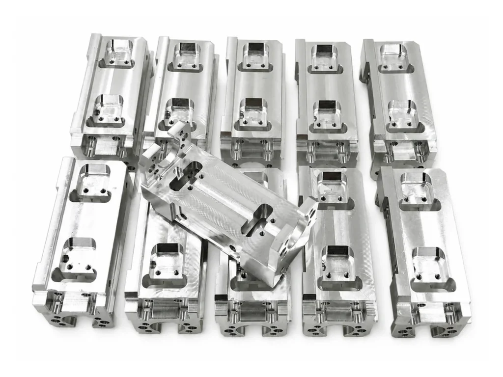
A second 6061-T6 robotic joint component was produced by 5-axis CNC machining in a low-volume batch. Critical requirements included an H7 bore, controlled parallelism and perpendicularity, and stable relationships between the bore and mounting features.
The parts were supplied in the as-machined condition and critical geometrical relationships were checked by CMM. Repeat production also required drawing revision control, first-off approval and in-process sampling.
RFQ Checklist for Robotic Joint Parts
- A usable 3D CAD model.
- A controlled 2D drawing with tolerances, datums, threads, surface finish and GD&T.
- Material grade and condition.
- Prototype or production quantity.
- Bearing, shaft and locating-component information where relevant to the interface.
- Surface treatment, masking and post-treatment machining requirements.
- Critical dimensions and any 100 percent inspection requirements.
- CMM report, sampling and documentation requirements.
- The final assembly and inspection state.
Frequently Asked Questions
Does H7 mean +/-0.01 mm?
No. The H7 tolerance width depends on the nominal bore diameter. It cannot be converted into one fixed plus-or-minus value without the size range.
Does an H7 bore guarantee correct bearing assembly?
No. Bearing selection, bore form, position, axis orientation, surface condition, temperature and the mating-component requirements also matter.
Does every robotic joint require 5-axis machining?
No. The appropriate route may be 3-axis, indexed 3+2, 5-axis, turning, mill-turn or a combined process depending on geometry and requirements.
Can a bore gauge inspect position or perpendicularity?
No. A bore gauge primarily checks diameter. Position, orientation and datum relationships normally require CMM inspection or a suitable dedicated gauge.
Why machine a bore after anodizing?
Surface treatment may affect the available fit. Post-treatment machining can restore the required bore size and, where necessary, control the relationship between the bore and a mounting face.
Does every order include a CMM report?
A full dimensional inspection report and material documentation are provided with each order. The CMM inspection scope and CMM report are confirmed during quotation.
Control the Bore and the Assembly Datum Together
Robotic joint quality should not be judged from one H7 bore size alone. Bearing bores, locating holes, mounting faces, datum relationships, surface treatment and inspection methods need to be reviewed as one assembly system.
Send the 3D model, controlled drawing, material, quantity and inspection requirements. SAMSHION can review the machining route, critical datums and verification plan through our custom CNC machining services and robotics manufacturing services.