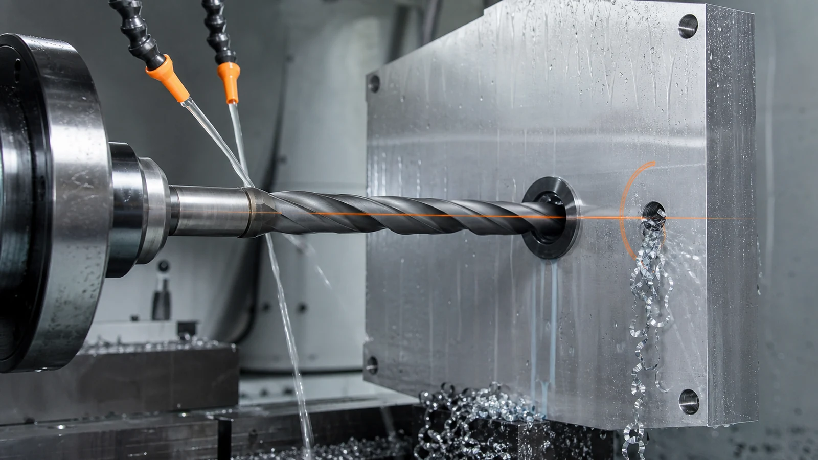
As drilling depth increases, small errors at entry grow into runout, drift, taper, poor finish or tool failure. Chips remain in contact longer, coolant has farther to travel and the finished surface becomes harder to inspect.
A reliable plan begins with the functional bore requirement and available access. Hole diameter, total depth, blind or through condition, straightness, position, finish, material and production quantity determine whether conventional drilling, a guided deep-hole process, boring, reaming or another route is appropriate.
Scope, Search Intent and Technical Boundary
This article begins where hole depth makes entry guidance, chip evacuation, coolant delivery, thermal load, axis drift or full-depth measurement difficult. It does not define one universal length-to-diameter threshold and does not promise gundrilling capability for every material or geometry. For independent cutting-tool application principles, consult the Sandvik Coromant deep-hole machining application guide.
This is not a second general hole-making or tolerance comparison. Use our CNC hole tolerance guide to compare drilling, reaming and boring and to specify diameter, position and orientation. Use this deep-hole article when depth makes guidance, coolant, chip evacuation, bore drift, internal condition and full-depth inspection the dominant risks.
Key Takeaways
- Specify the bore function, not only diameter and depth.
- Provide a stable entry and practical tool guidance.
- Plan coolant delivery and chip evacuation for the actual material.
- Separate rough drilling from finishing when accuracy requires it.
- Define how diameter, straightness, position and finish will be verified.
Classify the Hole and Its Functional Requirement
A fluid passage, bearing bore, gun-drilled channel and clearance hole need different control of diameter, straightness, finish and cleanliness. This article defines the feature-level review; the broader supplier capability, materials and project workflow remain on SAMSHION’s CNC machining services page.
Stabilize Entry, Guidance and Workholding
A flat, perpendicular entry and rigid datum scheme help prevent the initial angular error that grows with depth. For the corresponding manufacturing decision and capability context, consult SAMSHION’s CNC milling services.
Control Chips, Coolant and Thermal Load
Pecking, through-tool coolant and dedicated deep-hole systems manage chips differently; the correct method depends on material and geometry.
Select Roughing and Finishing Operations
Drilling may create the passage while boring, reaming, honing or another controlled process protects the final functional requirement. The purpose here is to plan stock, alignment and access for a deep feature, not to repeat a general comparison of hole-making methods. When a bore is produced from the rotational axis of a turned component, review access and datum transfer with the relevant CNC turning services capability.
Inspect Diameter, Drift and Internal Condition
Inspection access must be planned before machining because an entrance plug gauge cannot prove the complete bore path. Use the GD&T guide to define datum-based position and orientation, and use the CNC machining inspection guide to select reporting and traceability. The deep-hole plan must still identify which diameters, depths, axis locations, internal surfaces and cleanliness conditions are actually verified.
Engineering Variables to Confirm Before Quotation
Diameter, total depth and length-to-diameter ratio
Confirm diameter, total depth and length-to-diameter ratio before quotation. Evaluate it against hole diameter, axis drift, breakthrough condition, internal finish and cleanliness. Record the agreed value, part condition and acceptance stage on the controlled drawing or DFM record so workholding, drilling, bore finishing, cleaning and dimensional inspection use the same requirement.
Blind depth, breakthrough and allowable drill point
Confirm blind depth, breakthrough and allowable drill point before quotation. Evaluate it against hole diameter, axis drift, breakthrough condition, internal finish and cleanliness. Record the agreed value, part condition and acceptance stage on the controlled drawing or DFM record so workholding, drilling, bore finishing, cleaning and dimensional inspection use the same requirement.
Material chip form and work-hardening tendency
Confirm material chip form and work-hardening tendency before quotation. Evaluate it against hole diameter, axis drift, breakthrough condition, internal finish and cleanliness. Record the agreed value, part condition and acceptance stage on the controlled drawing or DFM record so workholding, drilling, bore finishing, cleaning and dimensional inspection use the same requirement.
Entry angle, cross holes and interrupted regions
Confirm entry angle, cross holes and interrupted regions before quotation. Evaluate it against hole diameter, axis drift, breakthrough condition, internal finish and cleanliness. Record the agreed value, part condition and acceptance stage on the controlled drawing or DFM record so workholding, drilling, bore finishing, cleaning and dimensional inspection use the same requirement.
Straightness, position, diameter and surface requirement
Confirm straightness, position, diameter and surface requirement before quotation. Evaluate it against hole diameter, axis drift, breakthrough condition, internal finish and cleanliness. Record the agreed value, part condition and acceptance stage on the controlled drawing or DFM record so workholding, drilling, bore finishing, cleaning and dimensional inspection use the same requirement.
Machine travel, coolant pressure and inspection access
Confirm machine travel, coolant pressure and inspection access before quotation. Evaluate it against hole diameter, axis drift, breakthrough condition, internal finish and cleanliness. Record the agreed value, part condition and acceptance stage on the controlled drawing or DFM record so workholding, drilling, bore finishing, cleaning and dimensional inspection use the same requirement.
Failure Modes and Root-Cause Diagnosis
The drill enters on angle and the exit misses position
When the drill enters on angle and the exit misses position, inspect entry condition, tool runout, chip form, coolant delivery, thermal growth and workholding stability. Compare the affected part with a controlled reference and change one suspected variable at a time. Retain the failed part, process record and measurement evidence until the root cause is confirmed.
Packed chips score the bore or break the tool
When packed chips score the bore or break the tool, inspect entry condition, tool runout, chip form, coolant delivery, thermal growth and workholding stability. Compare the affected part with a controlled reference and change one suspected variable at a time. Retain the failed part, process record and measurement evidence until the root cause is confirmed.
Heat produces taper or dimensional drift
When heat produces taper or dimensional drift, inspect entry condition, tool runout, chip form, coolant delivery, thermal growth and workholding stability. Compare the affected part with a controlled reference and change one suspected variable at a time. Retain the failed part, process record and measurement evidence until the root cause is confirmed.
A gauge verifies diameter near the mouth but misses deeper damage
When a gauge verifies diameter near the mouth but misses deeper damage, inspect entry condition, tool runout, chip form, coolant delivery, thermal growth and workholding stability. Compare the affected part with a controlled reference and change one suspected variable at a time. Retain the failed part, process record and measurement evidence until the root cause is confirmed.
Process Controls for a Repeatable Result
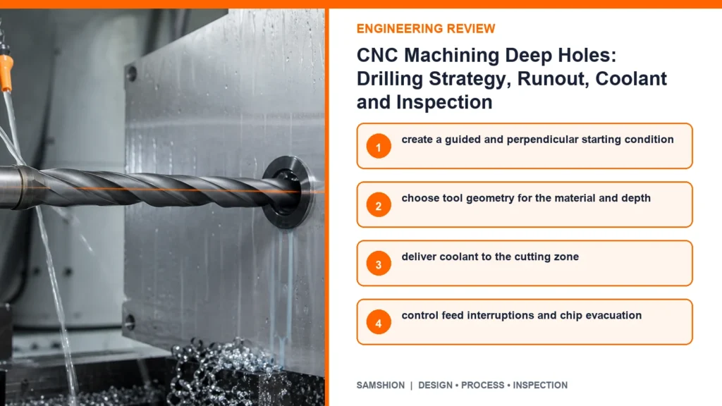
Create a guided and perpendicular starting condition
Implement create a guided and perpendicular starting condition as a documented process control. Record tool identity and life, setup, spindle and feed values, peck or continuous cycle, coolant pressure and part number. Verify the control on the first article, then define the check frequency and reaction limit for repeat production.
Choose tool geometry for the material and depth
Implement choose tool geometry for the material and depth as a documented process control. Record tool identity and life, setup, spindle and feed values, peck or continuous cycle, coolant pressure and part number. Verify the control on the first article, then define the check frequency and reaction limit for repeat production.
Deliver coolant to the cutting zone
Implement deliver coolant to the cutting zone as a documented process control. Record tool identity and life, setup, spindle and feed values, peck or continuous cycle, coolant pressure and part number. Verify the control on the first article, then define the check frequency and reaction limit for repeat production.
Control feed interruptions and chip evacuation
Implement control feed interruptions and chip evacuation as a documented process control. Record tool identity and life, setup, spindle and feed values, peck or continuous cycle, coolant pressure and part number. Verify the control on the first article, then define the check frequency and reaction limit for repeat production.
Leave planned stock for the finishing operation
Implement leave planned stock for the finishing operation as a documented process control. Record tool identity and life, setup, spindle and feed values, peck or continuous cycle, coolant pressure and part number. Verify the control on the first article, then define the check frequency and reaction limit for repeat production.
Validate the complete bore with an appropriate measurement method
Implement validate the complete bore with an appropriate measurement method as a documented process control. Record tool identity and life, setup, spindle and feed values, peck or continuous cycle, coolant pressure and part number. Verify the control on the first article, then define the check frequency and reaction limit for repeat production.
Inspection Strategy and Acceptance Evidence
Diameter at accessible depths
Evaluate diameter at accessible depths using depth-capable bore measurement, entrance and exit position checks, straightness evaluation, borescope review and cleanliness verification. State the part condition, datum or reference, acceptance limit and actual result. Keep the result traceable to machine setup, tool batch, part serial or lot and inspection report.
Entry-to-exit position and axis direction
Evaluate entry-to-exit position and axis direction using depth-capable bore measurement, entrance and exit position checks, straightness evaluation, borescope review and cleanliness verification. State the part condition, datum or reference, acceptance limit and actual result. Keep the result traceable to machine setup, tool batch, part serial or lot and inspection report.
Straightness or drift relative to datums
Evaluate straightness or drift relative to datums using depth-capable bore measurement, entrance and exit position checks, straightness evaluation, borescope review and cleanliness verification. State the part condition, datum or reference, acceptance limit and actual result. Keep the result traceable to machine setup, tool batch, part serial or lot and inspection report.
Surface and chip damage using a borescope
Evaluate surface and chip damage using a borescope using depth-capable bore measurement, entrance and exit position checks, straightness evaluation, borescope review and cleanliness verification. State the part condition, datum or reference, acceptance limit and actual result. Keep the result traceable to machine setup, tool batch, part serial or lot and inspection report.
Cleanliness and blockage of fluid passages
Evaluate cleanliness and blockage of fluid passages using depth-capable bore measurement, entrance and exit position checks, straightness evaluation, borescope review and cleanliness verification. State the part condition, datum or reference, acceptance limit and actual result. Keep the result traceable to machine setup, tool batch, part serial or lot and inspection report.
Cost, Lead Time and Quotation Transparency
Special long-reach or gundrilling equipment
Treat special long-reach or gundrilling equipment as a separate quotation driver when it changes special tooling, cycle time, tool monitoring, bore finishing, cleaning or special inspection. State what is included, the assumed acceptance evidence and which design or process change would require requotation.
Slow cycle time and tool-risk monitoring
Treat slow cycle time and tool-risk monitoring as a separate quotation driver when it changes special tooling, cycle time, tool monitoring, bore finishing, cleaning or special inspection. State what is included, the assumed acceptance evidence and which design or process change would require requotation.
Secondary honing, reaming or bore finishing
Treat secondary honing, reaming or bore finishing as a separate quotation driver when it changes special tooling, cycle time, tool monitoring, bore finishing, cleaning or special inspection. State what is included, the assumed acceptance evidence and which design or process change would require requotation.
Special probes, air gauging or destructive qualification
Treat special probes, air gauging or destructive qualification as a separate quotation driver when it changes special tooling, cycle time, tool monitoring, bore finishing, cleaning or special inspection. State what is included, the assumed acceptance evidence and which design or process change would require requotation.
A Practical Engineering Review Sequence
Start by classifying the hole: diameter, true drilled length, blind or through condition, entry and exit geometry, intersecting passages and the functional requirement for diameter, position, straightness and finish.
Then review the complete drilling system. Check entry support, tool guidance, spindle runout, holder condition, coolant delivery, chip evacuation and workholding before selecting the cycle or increasing feed.
Finally, inspect the entire functional depth rather than only the mouth. Correlate diameter, axis drift, internal condition and cleanliness with the tool and process record so a hidden defect cannot pass on a single plug-gauge result.
RFQ and DFM Checklist
- 3D model and controlled drawing with hole diameter, depth and datum scheme
- Blind or through condition, drill-point allowance and breakthrough requirement
- Material grade, heat treatment and expected chip behavior
- Entry angle, cross holes, internal intersections and exit condition
- Diameter, position, straightness, cylindricity and surface-finish limits
- Cleanliness, burr and blockage acceptance requirements
- Quantity, traceability and permitted inspection method or sectioning plan
Frequently Asked Questions
What counts as a deep hole?
The practical threshold depends on diameter, tool family, material, access and required accuracy. Final acceptance depends on the stated datum, delivered state and inspection approach.
Does peck drilling always improve chip evacuation?
Not always; repeated re-entry can add time and marks, while some tool systems are designed for continuous feed. Confirm the project-specific answer from the controlled drawing and the actual material condition.
Can a long hole be held straight by reaming?
Reaming generally follows the existing path and is not a universal correction for substantial drift. Confirm the project-specific answer from the controlled drawing and the actual material condition.
How is deep-hole runout inspected?
Options depend on access and may include entry-exit checks, probes, air gauges, borescopes or dedicated metrology. The general rule does not replace a feasibility review of the complete geometry and acceptance method.
Should a blind bore include drill-point allowance?
Yes, the drawing should distinguish usable cylindrical depth from tool-tip geometry. The general rule does not replace a feasibility review of the complete geometry and acceptance method.
Get an Engineering Review
Upload the native CAD model, controlled drawing, material specification, quantity and required finish for a project-specific review of CNC machining deep holes.
For a review of CNC machining deep holes, send the native CAD model, controlled drawing, material specification, quantity, finishing route and required acceptance records. SAMSHION’s engineering team can return project-specific DFM questions and documented quotation assumptions before production begins. When the model and drawing are ready, use request a deep-hole feasibility review and include the material, quantity, finish and inspection requirements.