CNC plastic prototypes do not always have to be machined as one continuous piece. When undercuts, deep grooves or difficult internal features restrict tool access, machining separate sections and bonding them can be an option. The decision starts with what the prototype must prove. A model for appearance and assembly review has different requirements from a part intended for strength testing.
At SAMSHION, we propose splitting suitable ABS, PC or ABS/PC prototypes when the geometry is difficult to machine and the project has no strength requirement. We send the customer the proposed split arrangement before proceeding. If one-piece construction is mandatory, we assess five-axis machining. Where that still cannot produce the geometry, we recommend drawing changes for the customer to approve.
What Splitting a CNC Prototype Means
A manufacturing split divides a component that is modeled as one part into sections that can be machined separately. Those sections are then located and bonded to reproduce the intended overall shape. This introduces a joint that was not present in the original solid model, so it must be an agreed manufacturing decision.
This is different from assembling parts that were already separate in the design. An upper housing and a removable lower cover are ordinary product components. Bonding that cover permanently would change its function. Similarly, a painted surface can conceal a manufacturing seam, but it does not turn a bonded part back into uninterrupted parent material.
Why Some Plastic Parts Are Difficult to Machine in One Piece
In plastic prototype machining, access is more than the direction shown in a CAD view. The cutting edge must reach the surface, the tool and holder need clearance, and the remaining material must be supported during cutting. A narrow opening can prevent a practical tool from reaching a wider internal feature.
None of these features automatically requires bonding. Some can be made in one piece with a different setup or a more suitable tool. For the depth and access questions specifically, our deep pocket machining guide provides additional context. The decision here is whether changing the manufacturing route still gives you a useful prototype.
When the Prototype Must Remain in One Piece
State a one-piece requirement before quotation if the sample will be used to assess strength or if joints are prohibited by the design. Also disclose pressure, sealing, repeated flexing, impact or screw-tightening tests. These requirements can place demands on a joint that an appearance-oriented split prototype was never intended to meet. Our non-strength split-and-bond route should not be substituted for such testing.
Five-axis machining provides additional approach directions, which can make some otherwise difficult surfaces accessible. Autodesk demonstrates undercut machining using a five-axis toolpath in its machining undercuts guidance. This does not mean every internal shape becomes machinable. A cutter still needs a physical entry path and sufficient clearance for the tool assembly.
Our sequence is straightforward. We first establish whether splitting is acceptable. If the customer requires an integral part, we assess five-axis CNC machining. If access is still impossible, we explain the obstruction and propose a design-for-manufacturing change, such as opening access or changing an obstructing feature. The customer must approve any change to the drawing before it is used for production.
What to Confirm in a Split Proposal
A useful proposal shows the section boundaries, how the pieces will be located, and where the completed joint will sit. It should distinguish permanent bonding from any covers or components that must remain removable. The customer should be able to see whether a proposed seam crosses a visible face, mounting hole, sealing area or mating edge.
Prefer a split that opens access to the difficult geometry without unnecessarily dividing critical features. Where practical, keeping a related hole pattern or mating surface in the same machined section avoids making that relationship depend on alignment across a bond. If a critical relationship does cross the split, identify it explicitly for final checking.
Do not choose the split line solely because it is easy to hide with paint. It must also allow machining, positioning, bonding and the agreed inspection. A concealed internal seam may still interfere with a mating component. A visually tidy external seam may be unsuitable if it passes through an area used to assess mechanical behavior.
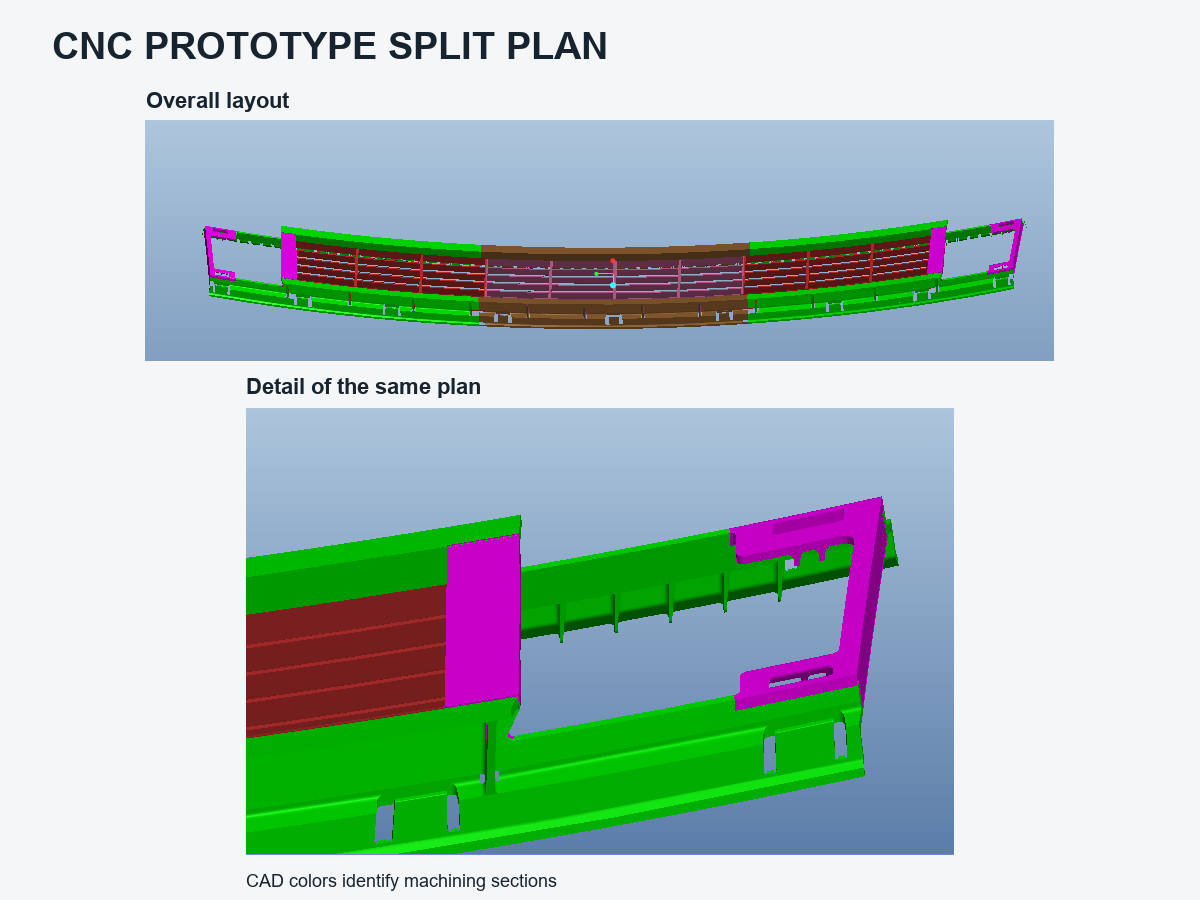
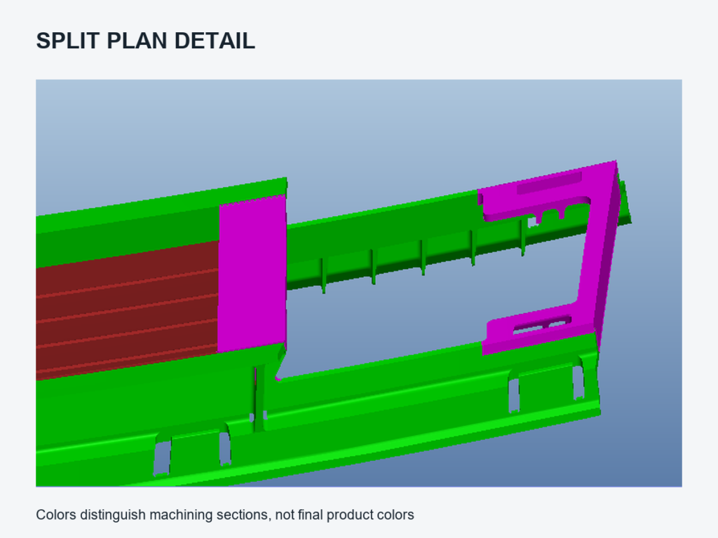
The color-coded CAD detail below shows how a split proposal can make the section boundaries visible for review. It is a close-up of the overall plan in the cover image. The colors distinguish machining sections rather than finished surface colors. The drawing view alone does not specify the adhesive or prove the performance of the completed joint.
How the Sections Are Located Before Bonding
SAMSHION uses steps, locating pin holes, mating locating features such as registers, or fixtures according to the part. These methods are alternatives or combinations, not a requirement to add every type of locator to every prototype.
- Steps and registers provide mating surfaces that help position one section relative to another.
- Locating pin holes can help control alignment when the surrounding geometry permits suitable locations.
- A fixture supports and holds the sections in the intended relationship during the joining operation.
The locating scheme must be consistent with the dimensions that matter on the completed part. Aligning the outside edges alone may not align an internal mounting pattern. Additional holes or steps also need review if they affect the customer geometry. A fixture can sometimes provide positioning without adding permanent locating features to the delivered part.
Bond-line allowance is not the same as paint allowance. The required joining clearance depends on the selected adhesive system and joint arrangement; there is no single gap value specified for all of the prototypes discussed here. The finished overall size must account for the joint, rather than simply adding together the nominal dimensions of the separate sections.
Choose a Bonding System for the Specified Plastic
ABS, polycarbonate and ABS/PC blends are the materials we commonly consider for this route. That describes our typical project selection, not a claim that any adhesive will work with every grade. The actual substrate, adhesive, surface preparation and subsequent finishing process must be compatible.
For example, a material being bondable does not remove the possibility of surface damage or chemical incompatibility. Ensinger guidance on bonding plastics recommends application-specific testing and consulting the adhesive supplier, and warns of stress cracking in amorphous plastics. Do not substitute a different plastic or glue solely because it looks similar.
If a material grade is mandatory for a later validation stage, state that requirement rather than accepting a change to simplify bonding. A more easily manufactured sample is not useful if the material change prevents it from answering the original engineering question.
Seam Repair Sanding and Painting
After joining, we repair and dress the seam, sand the surface, and use filler when needed before the specified painting process. These steps address the visible transition between sections. They do not justify shifting a hole, rounding off a fitting edge or removing material from a critical surface to make a seam look smoother.
Agree which surfaces are important to the appearance review and what reference the customer will use. A painted display model, an unpainted sample and a clear component have different acceptance conditions. In particular, opaque paint should not be offered as a way to satisfy a requirement for a transparent, visually continuous part.
The ABS prototype shown below was photographed immediately after bonding, before any seam repair or sanding. The accompanying close-up highlights the bonding trace with the original red annotation. This is an intermediate manufacturing condition, not the finished cosmetic surface.
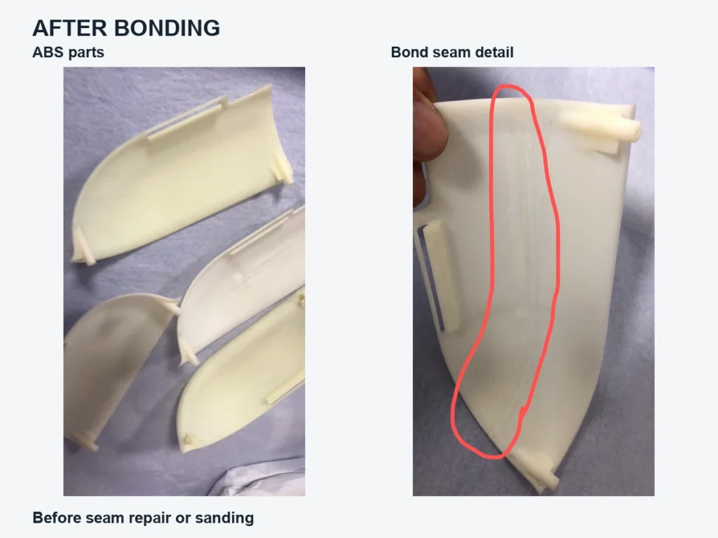
The visible seam helps explain why joining and surface finishing are separate operations. Its appearance at this stage should not be confused with the agreed appearance after seam preparation and painting. These photographs document the bonding stage; they do not demonstrate dimensional acceptance or joint strength.
Check the Completed Prototype as Well as the Separate Sections
Two sections can each meet their individual dimensions and still be misaligned after joining. SAMSHION checks the overall dimensions, hole positions or trial assembly fit as applicable, in addition to appearance. These checks address the completed prototype rather than treating a smooth painted surface as sufficient evidence of accuracy.
Identify dimensions that cross the joint, such as spacing between mounting holes on different sections or the overall width between opposing faces. Provide a mating part or assembly model where a fit check is important. State whether the requirement applies before paint or to the finished coated part, since the final surface condition can affect the fit.
Trial assembly should reflect the agreed purpose and handling of the sample. If it includes significant tightening loads, snap-fit cycling or another mechanical demand, disclose that before approving a non-strength prototype. A successful visual or fit review is not a strength qualification, and one-piece CNC machining by itself is not a substitute for a defined test either.
Compare the Complete Route Before Assuming a Cost Saving
Splitting may make difficult machining more practical, but it adds locating features or fixture work, joining, seam finishing and final checks. A part with extensive cosmetic repair can lose the machining-time advantage that prompted the split. Compare the finished deliverable, including the permitted joint locations and appearance standard, rather than comparing only cutting time.
Where both routes are feasible, ask what is included in the one-piece and split quotations. Neither lower price nor shorter delivery should be promised without reviewing the actual work. If the sample must remain integral, a cheaper bonded alternative does not meet the same requirement and should not be presented as an equivalent offer.
What to Send for a Useful CNC Prototype Review
Send the complete 3D model and a drawing that identifies the critical dimensions, then explain the intended review. A short statement such as “appearance and light trial assembly only, no strength testing” is more useful than simply calling the part a prototype. If that does not describe your application, state the actual loads or tests instead.
- State whether bonding is allowed, prohibited or subject to approval of a proposed split.
- Mark surfaces and functional features where a seam is unacceptable, and identify parts that must remain removable.
- Specify the material grade, quantity and finish, including any clear or unpainted areas.
- Identify hole relationships, overall dimensions and mating parts that need checking after joining and finishing.
- Explain whether geometry changes may be proposed and who will approve a revised drawing.
Frequently Asked Questions
Will every undercut require splitting
No. Another setup, a suitable cutting tool or five-axis access may allow one-piece machining. Splitting is considered when it addresses a real access or manufacturing difficulty and the prototype purpose permits a bonded joint.
Will the split line remain visible after painting
Seam repair, sanding and filler where necessary can improve the transition before paint. The acceptable result depends on the surface and agreed visual reference. Do not assume that every seam will be invisible under every lighting condition or finish.
Can the finished bonded prototype be disassembled
A permanent manufacturing bond is not a serviceable assembly joint. If access to electronics or internal components must be retained, identify the required removable covers before approving the split proposal. Do not expect to separate a bonded section without damaging it.
Can a bonded prototype be used for a strength test
The split-and-bond route described here is offered for projects without strength requirements. It should not be used as evidence of the strength of an integral design. Specify the test objective so that the material and manufacturing route can be chosen for that purpose.
Is splitting always cheaper than five axis machining
No. The comparison must include fixtures, bonding, seam repair, painting and inspection as well as machining. A simple one-piece route can be preferable to a split that creates extensive manual work. The quotation must compare the same agreed finished condition.
What happens if I do not allow splitting
Tell us before production. We assess whether five-axis CNC can make the integral part. If it cannot, we provide DFM suggestions for changing the obstructing geometry. We do not treat silence as approval to introduce a bonded joint or change the drawing.
Discuss the Manufacturing Route Before Cutting Starts
For a CNC machining project, the useful question is whether the chosen route preserves what you need to learn from the sample. Send your CAD files for review and tell us whether joints are allowed. We can then discuss an approved split arrangement, assess one-piece machining, or identify the drawing changes needed to make the part accessible.