At the end of a bend, material cannot continue flowing as if the flange were infinitely wide. If the flat pattern ends abruptly at the bend zone, the corner may tear, pull, bulge or leave a sharp irregular edge.
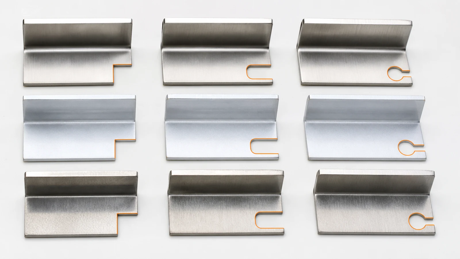
A bend relief is a deliberate cut that separates the moving flange from adjacent material. Its shape and extent should reflect sheet thickness, inside radius, material behavior, grain direction, finishing and the desired corner appearance.
Scope, Search Intent and Technical Boundary
This article focuses on relief geometry at bend ends and corners. It is distinct from the general bending service page and the hole-to-bend article in the same publication batch. For an additional authoritative reference, consult SOLIDWORKS sheet metal design documentation.
Apply the guidance to quotation and first-article planning for sheet metal bend relief design; do not treat illustrative values as guaranteed tolerances.
Key Takeaways
- Use relief where a bend terminates beside unbent material.
- Extend the relief far enough to clear the active bend zone.
- Avoid sharp relief roots when cracking or fatigue matters.
- Coordinate relief with welding, sealing and cosmetic corner requirements.
- Inspect the formed state, not only the laser-cut flat pattern.
Why Flange Ends Need Controlled Material Flow
The outer surface stretches while the inner surface compresses, and the transition at a bend end creates a localized three-dimensional strain state. For the corresponding manufacturing decision and capability context, consult SAMSHION’s manufacturing materials guide.
Compare Rectangular, Obround and Tear-Stop Reliefs
Straight slots are simple, while radiused ends can reduce stress concentration and improve repeatability in crack-sensitive materials. For the corresponding manufacturing decision and capability context, consult SAMSHION’s CNC press brake bending services.
Size Relief from the Actual Bend Zone
Relief width and depth should account for thickness, inside radius, tooling and tolerance rather than a decorative CAD notch. For the corresponding manufacturing decision and capability context, consult SAMSHION’s laser cutting services.
Coordinate Reliefs at Corners and Seams
Two adjacent flanges, hems, welds and corner gaps can interact with the same relief and change appearance or sealing. For the corresponding manufacturing decision and capability context, consult SAMSHION’s sheet metal workshop guide.
Inspect Formed Corners after Cutting and Finishing
A clean flat blank can still tear or bulge during bending, and coating can reveal edge irregularity later. For the corresponding manufacturing decision and capability context, consult SAMSHION’s surface finishing services.
Engineering Variables to Confirm Before Quotation
Sheet thickness and material elongation
For sheet metal bend relief design, sheet thickness and material elongation requires an explicit engineering decision. Make the functional intent visible before tooling is selected. Ask which function depends on it, which datum or material state establishes it, and at what production stage it will be accepted. Its interpretation changes datum selection, setup count and verification effort. Quote alternatives separately when more than one technically credible interpretation exists. Available grades, stock forms and supplied conditions can be cross-checked against the sheet metal fabrication services before quotation.
Inside bend radius and selected tooling
For sheet metal bend relief design, inside bend radius and selected tooling requires an explicit engineering decision. Use this requirement to frame the first technical review. Ask which function depends on it, which datum or material state establishes it, and at what production stage it will be accepted. It influences whether the feature is produced and accepted before or after secondary finishing. A written assumption lets the buyer compare suppliers on an equivalent technical basis.
Grain direction relative to the bend
For sheet metal bend relief design, grain direction relative to the bend requires an explicit engineering decision. Treat this as an RFQ input, not a shop-floor surprise. Ask which function depends on it, which datum or material state establishes it, and at what production stage it will be accepted. A different answer may require different stock, clamping pressure or inspection equipment. If the customer cannot confirm it, state the working assumption and its commercial effect in writing.
Relief root geometry and cut-edge quality
For sheet metal bend relief design, relief root geometry and cut-edge quality requires an explicit engineering decision. Do not allow a default title-block tolerance to answer this question indirectly. Ask which function depends on it, which datum or material state establishes it, and at what production stage it will be accepted. The result governs how much process evidence is needed to support the quotation. Record the agreed interpretation beside the revision so later orders do not reopen the same ambiguity.
Relationship to adjacent flange, seam or weld
For sheet metal bend relief design, relationship to adjacent flange, seam or weld requires an explicit engineering decision. Confirm the delivered-state requirement before estimating cycle time. Ask which function depends on it, which datum or material state establishes it, and at what production stage it will be accepted. The decision can move a feature from a routine check to a controlled first-article characteristic. Quote alternatives separately when more than one technically credible interpretation exists.
Post-form coating and cosmetic standard
For sheet metal bend relief design, post-form coating and cosmetic standard requires an explicit engineering decision. Reconcile the model, drawing and purchase specification at this point. Ask which function depends on it, which datum or material state establishes it, and at what production stage it will be accepted. A clear answer prevents manufacturing convenience from replacing functional intent. Record the agreed interpretation beside the revision so later orders do not reopen the same ambiguity.
Failure Modes and Root-Cause Diagnosis
The sheet tears from a sharp relief root
A characteristic failure for sheet metal bend relief design occurs when the sheet tears from a sharp relief root. The observation is evidence, not yet a root cause. Evaluate material behavior, support, cutter condition, programmed sequence and the measurement alignment as separate hypotheses. Inspect a first-off part both before and after the relevant secondary operation. Update the setup sheet and inspection plan so the fix survives the next batch.
Material bulges into an assembly interface
A characteristic failure for sheet metal bend relief design occurs when material bulges into an assembly interface. The observation is evidence, not yet a root cause. Evaluate material behavior, support, cutter condition, programmed sequence and the measurement alignment as separate hypotheses. Separate geometry created by the toolpath from movement created by heat or fixture load. Confirm that the remedy does not transfer error to a mating feature or datum.
A relief is too short and the bend pulls the adjoining wall
A characteristic failure for sheet metal bend relief design occurs when a relief is too short and the bend pulls the adjoining wall. The observation is evidence, not yet a root cause. Evaluate material behavior, support, cutter condition, programmed sequence and the measurement alignment as separate hypotheses. Inspect a first-off part both before and after the relevant secondary operation. Do not hide the symptom with manual blending unless the drawing explicitly permits that edge condition.
Powder coating emphasizes an irregular or razor-sharp corner
A characteristic failure for sheet metal bend relief design occurs when powder coating emphasizes an irregular or razor-sharp corner. The observation is evidence, not yet a root cause. Evaluate material behavior, support, cutter condition, programmed sequence and the measurement alignment as separate hypotheses. Preserve the failed part condition long enough to distinguish cutting evidence from handling or finishing damage. If the cause remains uncertain, contain the lot and expand the trial before releasing more material.
Process Controls for a Repeatable Result
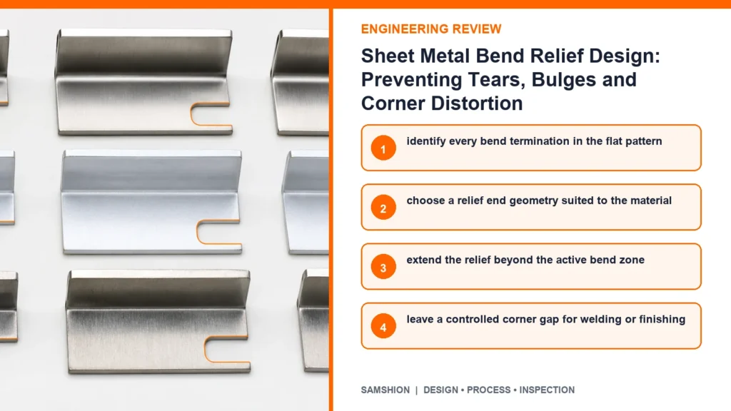
Identify every bend termination in the flat pattern
A process plan for sheet metal bend relief design can control this risk by choosing to identify every bend termination in the flat pattern. The action is useful only when it targets a named source of variation. Before release, consider access, local stiffness, heat flow and the acceptance condition of neighboring features. Verify that the method remains stable after tool change, unclamping or finishing. Repeat production should not depend on an operator remembering an undocumented exception.
Choose a relief end geometry suited to the material
A process plan for sheet metal bend relief design can control this risk by choosing to choose a relief end geometry suited to the material. The action is useful only when it targets a named source of variation. Before release, consider access, local stiffness, heat flow and the acceptance condition of neighboring features. Prove the control on the first article and retain the before-and-after evidence. Remove the control if trials show that it adds handling without reducing the targeted variation.
Extend the relief beyond the active bend zone
A process plan for sheet metal bend relief design can control this risk by choosing to extend the relief beyond the active bend zone. The action is useful only when it targets a named source of variation. Before release, consider access, local stiffness, heat flow and the acceptance condition of neighboring features. Prove the control on the first article and retain the before-and-after evidence. The inspector must evaluate the same condition the operator is controlling.
Leave a controlled corner gap for welding or finishing
A process plan for sheet metal bend relief design can control this risk by choosing to leave a controlled corner gap for welding or finishing. The action is useful only when it targets a named source of variation. Before release, consider access, local stiffness, heat flow and the acceptance condition of neighboring features. Prove the control on the first article and retain the before-and-after evidence. Remove the control if trials show that it adds handling without reducing the targeted variation.
Verify grain-sensitive parts in the intended blank orientation
A process plan for sheet metal bend relief design can control this risk by choosing to verify grain-sensitive parts in the intended blank orientation. The action is useful only when it targets a named source of variation. Before release, consider access, local stiffness, heat flow and the acceptance condition of neighboring features. Prove the control on the first article and retain the before-and-after evidence. Use the simplest method that reliably protects the stated function.
Approve a first formed sample before batch release
A process plan for sheet metal bend relief design can control this risk by choosing to approve a first formed sample before batch release. The action is useful only when it targets a named source of variation. Before release, consider access, local stiffness, heat flow and the acceptance condition of neighboring features. Use a short prototype trial first; formalize fixture, sampling and tool-life rules for repeat orders. Escalate a trend before it crosses the acceptance limit.
Inspection Strategy and Acceptance Evidence
Tear or crack condition at the relief root
Inspection of sheet metal bend relief design should explicitly address tear or crack condition at the relief root. First define the characteristic, datum reference and part condition represented by the result. Select contact geometry and measuring force that will not distort or bridge the feature. Report nominal, limits and actual result; do not substitute a certificate statement for measured data.
Formed flange angle beside the relief
Inspection of sheet metal bend relief design should explicitly address formed flange angle beside the relief. First define the characteristic, datum reference and part condition represented by the result. Use a functional gauge when fit matters more than a single isolated coordinate. For variable geometry, show the measurement locations instead of reporting one unexplained value. The available verification and reporting workflow is summarized in SAMSHION’s quality assurance.
Corner bulge and interference with mating parts
Inspection of sheet metal bend relief design should explicitly address corner bulge and interference with mating parts. First define the characteristic, datum reference and part condition represented by the result. Correlate shop-floor and final-inspection methods before using either for acceptance. Keep the measurement program and fixture revision with the inspection record.
Edge sharpness after deburring
Inspection of sheet metal bend relief design should explicitly address edge sharpness after deburring. First define the characteristic, datum reference and part condition represented by the result. Build the datum alignment exactly as defined on the controlled drawing. When results disagree, compare alignment, force, temperature and feature definition before averaging values.
Appearance after the specified coating
Inspection of sheet metal bend relief design should explicitly address appearance after the specified coating. First define the characteristic, datum reference and part condition represented by the result. Sample the locations and depths where process behavior can genuinely change. When results disagree, compare alignment, force, temperature and feature definition before averaging values.
Cost, Lead Time and Quotation Transparency
Additional laser or punch path complexity
In a quotation for sheet metal bend relief design, additional laser or punch path complexity can influence both lead time and total manufacturing cost. A prototype route may be economical once but unsuitable for a repeating order. State the assumed interpretation, included records and conditions that would trigger requotation.
Manual corner dressing
In a quotation for sheet metal bend relief design, manual corner dressing can influence both lead time and total manufacturing cost. Dedicated support or gauging may raise initial cost while lowering variation across a batch. Tie any cost-saving proposal to a controlled drawing revision.
Scrap from crack-sensitive material
In a quotation for sheet metal bend relief design, scrap from crack-sensitive material can influence both lead time and total manufacturing cost. It can add material preparation, a dedicated cutter or a separate verification step. Identify whether the commercial risk comes from capability, ambiguity or verification effort.
Welding and coating rework at poorly controlled corners
In a quotation for sheet metal bend relief design, welding and coating rework at poorly controlled corners can influence both lead time and total manufacturing cost. A prototype route may be economical once but unsuitable for a repeating order. Offer a DFM alternative only when it preserves assembly, sealing, load or appearance.
A Practical Engineering Review Sequence
Start with the function protected by sheet thickness and material elongation. Mark the related datums, interfaces and delivered-state requirements on the controlled drawing. The manufacturing review can then choose stock, setups and cutting access around that function instead of treating every dimension as equally critical.
Walk through the likely failure mechanism represented by this project: the sheet tears from a sharp relief root. Decide which evidence can reveal the problem earliest and which operation can still correct it. This ordering avoids discovering a predictable condition only after finishing or final inspection.
Use the first article to validate the proposed control, including the instruction to identify every bend termination in the flat pattern. The approval part must represent the intended material, fixture, program, secondary operations and measurement alignment. Feed the result back into the process record before releasing the balance of the order.
RFQ and DFM Checklist
- Native 3D CAD model plus a controlled 2D drawing for tolerances and notes
- Exact material grade, condition, stock preference and certification requirement
- Functional datums, mating components and genuinely critical characteristics
- Quantity, prototype or production intent, and expected repeat-order status
- Surface finish, coating, heat treatment, cleaning and marking requirements
- Inspection report, certificate, gauge or sampling requirements
- Any approved alternative geometry or process constraints
Additional Engineering Review Notes
A useful design-review exercise is to trace one requirement through the complete production route. For sheet metal bend relief design, examine sheet thickness and material elongation and ask how it could contribute to a condition in which material bulges into an assembly interface. One candidate action is to extend the relief beyond the active bend zone; however, its value must be demonstrated through edge sharpness after deburring. Use the failed condition to define a controlled trial, not as permission for an undocumented rework step. Also consider the commercial effect of additional laser or punch path complexity, because a technically sound route must be quoted with transparent assumptions. A control that cannot be checked objectively should be rewritten before it enters the setup sheet.
A practical supplier discussion can begin with one ambiguous or high-consequence feature. For sheet metal bend relief design, examine inside bend radius and selected tooling and ask how it could contribute to a condition in which a relief is too short and the bend pulls the adjoining wall. One candidate action is to leave a controlled corner gap for welding or finishing; however, its value must be demonstrated through appearance after the specified coating. Retain a marked image or inspection trace so the team is discussing the same location. Also consider the commercial effect of manual corner dressing, because a technically sound route must be quoted with transparent assumptions. Keep the approved method connected to the fixture, program and inspection revision.
The project team should test whether its acceptance rule still makes sense after all secondary operations. For sheet metal bend relief design, examine grain direction relative to the bend and ask how it could contribute to a condition in which powder coating emphasizes an irregular or razor-sharp corner. One candidate action is to verify grain-sensitive parts in the intended blank orientation; however, its value must be demonstrated through tear or crack condition at the relief root. Compare the result with a second part, setup or tool-life interval before declaring a systemic cause. Also consider the commercial effect of scrap from crack-sensitive material, because a technically sound route must be quoted with transparent assumptions. Escalate a trend at the warning limit instead of waiting for a rejected final result.
The project team should test whether its acceptance rule still makes sense after all secondary operations. For sheet metal bend relief design, examine relief root geometry and cut-edge quality and ask how it could contribute to a condition in which the sheet tears from a sharp relief root. One candidate action is to approve a first formed sample before batch release; however, its value must be demonstrated through formed flange angle beside the relief. Distinguish a dimensional nonconformance from a measurement-access or datum-alignment problem. Also consider the commercial effect of welding and coating rework at poorly controlled corners, because a technically sound route must be quoted with transparent assumptions. If the trial confirms the control, apply it to the remaining quantity and monitor the first repeat batch.
A useful design-review exercise is to trace one requirement through the complete production route. For sheet metal bend relief design, examine relationship to adjacent flange, seam or weld and ask how it could contribute to a condition in which material bulges into an assembly interface. One candidate action is to identify every bend termination in the flat pattern; however, its value must be demonstrated through corner bulge and interference with mating parts. Use the failed condition to define a controlled trial, not as permission for an undocumented rework step. Also consider the commercial effect of additional laser or punch path complexity, because a technically sound route must be quoted with transparent assumptions. A control that cannot be checked objectively should be rewritten before it enters the setup sheet.
Frequently Asked Questions
Does every sheet metal bend require a relief?
No. Relief is relevant where the bend terminates or interacts with adjacent material. Confirm the project-specific answer from the controlled drawing and the actual material condition.
Is a rectangular relief always cheaper?
It is simple to cut, but a radiused root may better control cracking or finishing risk. Treat this as planning guidance and document any project assumption in the quotation.
Can the relief stop exactly on the bend line?
That may leave material in the active deformation zone; the required extent should be reviewed with the bend process. The general rule does not replace a feasibility review of the complete geometry and acceptance method.
Should bend relief be added before or after unfolding?
The flat pattern and formed geometry should be checked together using the controlled sheet-metal model. Final acceptance depends on the stated datum, delivered state and inspection approach.
Does deburring change relief performance?
Aggressive edge rounding can change fit, but removing harmful burrs may improve formability and handling. The general rule does not replace a feasibility review of the complete geometry and acceptance method.
Get an Engineering Review
Upload the native CAD model, controlled drawing, material specification, quantity and required finish for a project-specific review of sheet metal bend relief design.
For a review of sheet metal bend relief design, send the native CAD model, controlled drawing, material specification, quantity, finishing route and required acceptance records. SAMSHION’s engineering team can return project-specific DFM questions and documented quotation assumptions before production begins. When the model and drawing are ready, use upload your DXF and STEP files and include the material, quantity, finish and inspection requirements.