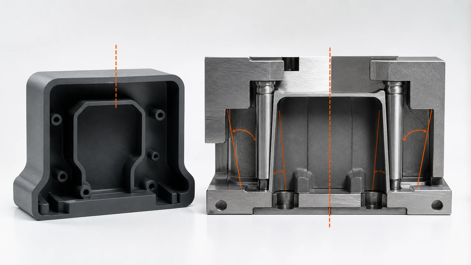
Draft lets the molded part move away from the cavity and core without prolonged rubbing, scuffing or excessive ejection force. The necessary amount is influenced by draw depth, resin shrinkage, polish direction, surface texture and tool construction.
A single blanket angle can therefore be misleading. Smooth outside walls, textured inside walls, ribs, bosses, shutoffs and side-action features should be reviewed separately.
Scope, Search Intent and Technical Boundary
This article is limited to release draft on injection-molded geometry. It does not replace the site’s general injection molding DFM or snap-fit content. For an additional authoritative reference, consult BASF injection molding guidance for draft and textured surfaces.
Apply the guidance to quotation and first-article planning for injection molding draft angle; do not treat illustrative values as guaranteed tolerances.
Key Takeaways
- Define the mold-pull direction before applying draft.
- Increase release allowance as texture depth and draw length increase.
- Review inside and outside surfaces separately because shrinkage changes their behavior.
- Do not use draft to hide an undercut that actually needs a side action.
- Approve cosmetic texture and draft together before cutting final steel.
Start with the True Mold-Pull Direction
Draft is measured relative to the direction in which each mold component releases, not simply the CAD global axis. For the corresponding manufacturing decision and capability context, consult SAMSHION’s injection molding shrinkage guide.
Coordinate Draft with Molded-In Texture
Texture adds microscopic and macroscopic undercut, increasing the release demand and risk of drag marks. For the corresponding manufacturing decision and capability context, consult SAMSHION’s surface finishes for molded parts.
Handle Ribs, Bosses and Deep Walls
Tall narrow features need local draft, fillets and ejection support without making functional interfaces too tapered. For the corresponding manufacturing decision and capability context, consult SAMSHION’s injection molding materials guide.
Inspect Draft, Drag and Cosmetic Acceptance
A measured angle alone does not prove acceptable release; scuffing, gloss change and deformation also matter.
Engineering Variables to Confirm Before Quotation
Mold-pull direction for each tool component
For injection molding draft angle, mold-pull direction for each tool component requires an explicit engineering decision. Treat this as an RFQ input, not a shop-floor surprise. Ask which function depends on it, which datum or material state establishes it, and at what production stage it will be accepted. It can alter support strategy, cutter access and the order of finishing operations. A written assumption lets the buyer compare suppliers on an equivalent technical basis. Available grades, stock forms and supplied conditions can be cross-checked against the plastic injection molding services before quotation.
Resin shrinkage onto cores
For injection molding draft angle, resin shrinkage onto cores requires an explicit engineering decision. Confirm the delivered-state requirement before estimating cycle time. Ask which function depends on it, which datum or material state establishes it, and at what production stage it will be accepted. It may determine whether a flexible prototype route remains suitable for repeat production. If the customer cannot confirm it, state the working assumption and its commercial effect in writing.
Draw depth and uninterrupted contact length
For injection molding draft angle, draw depth and uninterrupted contact length requires an explicit engineering decision. Reconcile the model, drawing and purchase specification at this point. Ask which function depends on it, which datum or material state establishes it, and at what production stage it will be accepted. It influences whether the feature is produced and accepted before or after secondary finishing. Where two documents disagree, obtain a controlled clarification before releasing material.
Surface texture depth and direction
For injection molding draft angle, surface texture depth and direction requires an explicit engineering decision. Confirm the delivered-state requirement before estimating cycle time. Ask which function depends on it, which datum or material state establishes it, and at what production stage it will be accepted. The result governs how much process evidence is needed to support the quotation. A written assumption lets the buyer compare suppliers on an equivalent technical basis.
Wall thickness and local stiffness during ejection
For injection molding draft angle, wall thickness and local stiffness during ejection requires an explicit engineering decision. Reconcile the model, drawing and purchase specification at this point. Ask which function depends on it, which datum or material state establishes it, and at what production stage it will be accepted. It influences whether the feature is produced and accepted before or after secondary finishing. If the customer cannot confirm it, state the working assumption and its commercial effect in writing.
Functional fits that limit permissible taper
For injection molding draft angle, functional fits that limit permissible taper requires an explicit engineering decision. Use this requirement to frame the first technical review. Ask which function depends on it, which datum or material state establishes it, and at what production stage it will be accepted. It influences whether the feature is produced and accepted before or after secondary finishing. Where two documents disagree, obtain a controlled clarification before releasing material.
Failure Modes and Root-Cause Diagnosis
A textured wall drags and produces gloss streaks
A characteristic failure for injection molding draft angle occurs when a textured wall drags and produces gloss streaks. The observation is evidence, not yet a root cause. Evaluate material behavior, support, cutter condition, programmed sequence and the measurement alignment as separate hypotheses. Use a controlled trial that changes one suspected mechanism while holding the remaining variables constant. Do not hide the symptom with manual blending unless the drawing explicitly permits that edge condition.
A deep core holds the part and bends it during ejection
A characteristic failure for injection molding draft angle occurs when a deep core holds the part and bends it during ejection. The observation is evidence, not yet a root cause. Evaluate material behavior, support, cutter condition, programmed sequence and the measurement alignment as separate hypotheses. Separate geometry created by the toolpath from movement created by heat or fixture load. Confirm that the remedy does not transfer error to a mating feature or datum.
An apparently drafted rib still creates a local undercut
A characteristic failure for injection molding draft angle occurs when an apparently drafted rib still creates a local undercut. The observation is evidence, not yet a root cause. Evaluate material behavior, support, cutter condition, programmed sequence and the measurement alignment as separate hypotheses. Check whether the indication follows the cutter, the setup, the material lot or the inspection alignment. Update the setup sheet and inspection plan so the fix survives the next batch.
A functional mating surface loses contact because taper was added without tolerance review
A characteristic failure for injection molding draft angle occurs when a functional mating surface loses contact because taper was added without tolerance review. The observation is evidence, not yet a root cause. Evaluate material behavior, support, cutter condition, programmed sequence and the measurement alignment as separate hypotheses. Use a controlled trial that changes one suspected mechanism while holding the remaining variables constant. Correct the mechanism and then revalidate the complete functional relationship.
Process Controls for a Repeatable Result
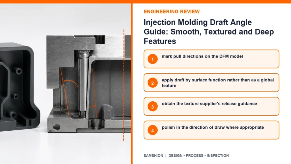
Mark pull directions on the DFM model
A process plan for injection molding draft angle can control this risk by choosing to mark pull directions on the DFM model. The action is useful only when it targets a named source of variation. Before release, consider access, local stiffness, heat flow and the acceptance condition of neighboring features. Prove the control on the first article and retain the before-and-after evidence. Use the simplest method that reliably protects the stated function.
Apply draft by surface function rather than as a global feature
A process plan for injection molding draft angle can control this risk by choosing to apply draft by surface function rather than as a global feature. The action is useful only when it targets a named source of variation. Before release, consider access, local stiffness, heat flow and the acceptance condition of neighboring features. Assign an operator check at the operation where the variable can still be corrected. Retain enough evidence to distinguish setup drift from material or tool variation.
Obtain the texture supplier's release guidance
A process plan for injection molding draft angle can control this risk by choosing to obtain the texture supplier’s release guidance. The action is useful only when it targets a named source of variation. Before release, consider access, local stiffness, heat flow and the acceptance condition of neighboring features. Link the method to the part revision, program revision and inspection revision. A stable process is demonstrated by evidence across parts, not by one favorable measurement.
Polish in the direction of draw where appropriate
A process plan for injection molding draft angle can control this risk by choosing to polish in the direction of draw where appropriate. The action is useful only when it targets a named source of variation. Before release, consider access, local stiffness, heat flow and the acceptance condition of neighboring features. Link the method to the part revision, program revision and inspection revision. If it changes a controlled requirement, customer approval comes before production release.
Distribute ejection force across stiff regions
A process plan for injection molding draft angle can control this risk by choosing to distribute ejection force across stiff regions. The action is useful only when it targets a named source of variation. Before release, consider access, local stiffness, heat flow and the acceptance condition of neighboring features. Link the method to the part revision, program revision and inspection revision. Escalate a trend before it crosses the acceptance limit.
Test representative texture and resin before final cosmetic approval
A process plan for injection molding draft angle can control this risk by choosing to test representative texture and resin before final cosmetic approval. The action is useful only when it targets a named source of variation. Before release, consider access, local stiffness, heat flow and the acceptance condition of neighboring features. Verify that the method remains stable after tool change, unclamping or finishing. Retain enough evidence to distinguish setup drift from material or tool variation.
Inspection Strategy and Acceptance Evidence
Actual angle relative to the controlled pull direction
Inspection of injection molding draft angle should explicitly address actual angle relative to the controlled pull direction. First define the characteristic, datum reference and part condition represented by the result. Correlate shop-floor and final-inspection methods before using either for acceptance. For variable geometry, show the measurement locations instead of reporting one unexplained value.
Drag marks and gloss change under agreed lighting
Inspection of injection molding draft angle should explicitly address drag marks and gloss change under agreed lighting. First define the characteristic, datum reference and part condition represented by the result. Use a functional gauge when fit matters more than a single isolated coordinate. Identify whether each result is measured, visually verified or supported only by material documentation. The available verification and reporting workflow is summarized in SAMSHION’s quality assurance.
Rib, boss and shutoff release condition
Inspection of injection molding draft angle should explicitly address rib, boss and shutoff release condition. First define the characteristic, datum reference and part condition represented by the result. Select contact geometry and measuring force that will not distort or bridge the feature. Retain traceability to the part revision and the production stage at which acceptance occurred.
Free-state deformation after ejection
Inspection of injection molding draft angle should explicitly address free-state deformation after ejection. First define the characteristic, datum reference and part condition represented by the result. Choose equipment whose uncertainty is small enough to support the stated decision. Retain traceability to the part revision and the production stage at which acceptance occurred.
Fit of tapered functional interfaces
Inspection of injection molding draft angle should explicitly address fit of tapered functional interfaces. First define the characteristic, datum reference and part condition represented by the result. Choose equipment whose uncertainty is small enough to support the stated decision. When results disagree, compare alignment, force, temperature and feature definition before averaging values.
Cost, Lead Time and Quotation Transparency
Side actions required by unresolved undercuts
In a quotation for injection molding draft angle, side actions required by unresolved undercuts can influence both lead time and total manufacturing cost. The quantity and cost of a scrapped blank change how much prevention is economically justified. Do not reduce price by silently omitting the requested acceptance evidence. The wider effect of setup, tolerance and documentation choices is explained in the rapid tooling services.
Mold polishing and texture rework
In a quotation for injection molding draft angle, mold polishing and texture rework can influence both lead time and total manufacturing cost. It may increase setup time, prove-out time or the risk allowance on expensive stock. Make the buyer aware when a local feature requirement dominates the economics of the complete part.
Extra ejection components
In a quotation for injection molding draft angle, extra ejection components can influence both lead time and total manufacturing cost. It can add material preparation, a dedicated cutter or a separate verification step. Make the buyer aware when a local feature requirement dominates the economics of the complete part.
Tool changes after texture has been applied
In a quotation for injection molding draft angle, tool changes after texture has been applied can influence both lead time and total manufacturing cost. The cost can move from machining into inspection programming, gauging or documentation. Compare flexible and dedicated production routes when order volume could justify either.
A Practical Engineering Review Sequence
Start with the function protected by mold-pull direction for each tool component. Mark the related datums, interfaces and delivered-state requirements on the controlled drawing. The manufacturing review can then choose stock, setups and cutting access around that function instead of treating every dimension as equally critical.
Walk through the likely failure mechanism represented by this project: a textured wall drags and produces gloss streaks. Decide which evidence can reveal the problem earliest and which operation can still correct it. This ordering avoids discovering a predictable condition only after finishing or final inspection.
Use the first article to validate the proposed control, including the instruction to mark pull directions on the DFM model. The approval part must represent the intended material, fixture, program, secondary operations and measurement alignment. Feed the result back into the process record before releasing the balance of the order.
RFQ and DFM Checklist
- Native 3D CAD model plus a controlled 2D drawing for tolerances and notes
- Exact material grade, condition, stock preference and certification requirement
- Functional datums, mating components and genuinely critical characteristics
- Quantity, prototype or production intent, and expected repeat-order status
- Surface finish, coating, heat treatment, cleaning and marking requirements
- Inspection report, certificate, gauge or sampling requirements
- Any approved alternative geometry or process constraints
Additional Engineering Review Notes
The project team should test whether its acceptance rule still makes sense after all secondary operations. For injection molding draft angle, examine mold-pull direction for each tool component and ask how it could contribute to a condition in which a deep core holds the part and bends it during ejection. One candidate action is to obtain the texture supplier’s release guidance; however, its value must be demonstrated through free-state deformation after ejection. Record the part state and operation where the observation first becomes visible. Also consider the commercial effect of side actions required by unresolved undercuts, because a technically sound route must be quoted with transparent assumptions. When the control affects fit or appearance, obtain approval through the drawing revision rather than email alone.
An additional risk review should connect the drawing statement to the evidence available at final acceptance. For injection molding draft angle, examine resin shrinkage onto cores and ask how it could contribute to a condition in which an apparently drafted rib still creates a local undercut. One candidate action is to polish in the direction of draw where appropriate; however, its value must be demonstrated through fit of tapered functional interfaces. Compare the result with a second part, setup or tool-life interval before declaring a systemic cause. Also consider the commercial effect of mold polishing and texture rework, because a technically sound route must be quoted with transparent assumptions. If the trial confirms the control, apply it to the remaining quantity and monitor the first repeat batch.
For repeat orders, convert the first-article lesson into a revision-controlled production instruction. For injection molding draft angle, examine draw depth and uninterrupted contact length and ask how it could contribute to a condition in which a functional mating surface loses contact because taper was added without tolerance review. One candidate action is to distribute ejection force across stiff regions; however, its value must be demonstrated through actual angle relative to the controlled pull direction. Distinguish a dimensional nonconformance from a measurement-access or datum-alignment problem. Also consider the commercial effect of extra ejection components, because a technically sound route must be quoted with transparent assumptions. Escalate a trend at the warning limit instead of waiting for a rejected final result.
A useful design-review exercise is to trace one requirement through the complete production route. For injection molding draft angle, examine surface texture depth and direction and ask how it could contribute to a condition in which a textured wall drags and produces gloss streaks. One candidate action is to test representative texture and resin before final cosmetic approval; however, its value must be demonstrated through drag marks and gloss change under agreed lighting. Preserve enough traceability to connect the observation to material lot, setup and program revision. Also consider the commercial effect of tool changes after texture has been applied, because a technically sound route must be quoted with transparent assumptions. Remove process steps that add handling but do not reduce the targeted source of variation.
The project team should test whether its acceptance rule still makes sense after all secondary operations. For injection molding draft angle, examine wall thickness and local stiffness during ejection and ask how it could contribute to a condition in which a deep core holds the part and bends it during ejection. One candidate action is to mark pull directions on the DFM model; however, its value must be demonstrated through rib, boss and shutoff release condition. Use the failed condition to define a controlled trial, not as permission for an undocumented rework step. Also consider the commercial effect of side actions required by unresolved undercuts, because a technically sound route must be quoted with transparent assumptions. A control that cannot be checked objectively should be rewritten before it enters the setup sheet.
Frequently Asked Questions
Is one degree of draft enough for every part?
No. Material, depth, texture, polish, tool condition and acceptance all change the requirement. Confirm the project-specific answer from the controlled drawing and the actual material condition.
Does a textured surface need more draft?
Usually the texture supplier and molder will require additional release allowance based on the texture. Final acceptance depends on the stated datum, delivered state and inspection approach.
Can zero draft work on a polished surface?
It may be possible locally in special circumstances, but should not be assumed without tool and ejection review. The general rule does not replace a feasibility review of the complete geometry and acceptance method.
Do ribs need draft?
Yes when they release from mold steel; thickness, height, spacing and ejection also require review. Treat this as planning guidance and document any project assumption in the quotation.
Is negative draft the same as an undercut?
A surface that locks against the pull direction generally requires redesign or another moving tool component. Treat this as planning guidance and document any project assumption in the quotation.
Get an Engineering Review
Upload the native CAD model, controlled drawing, material specification, quantity and required finish for a project-specific review of injection molding draft angle.
For a review of injection molding draft angle, send the native CAD model, controlled drawing, material specification, quantity, finishing route and required acceptance records. SAMSHION’s engineering team can return project-specific DFM questions and documented quotation assumptions before production begins. When the model and drawing are ready, use request an injection molding DFM review and include the material, quantity, finish and inspection requirements.