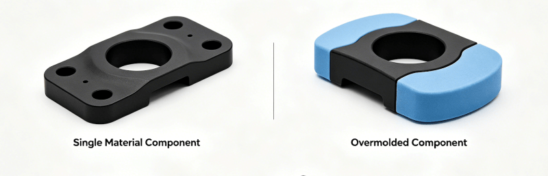
Overmolding combines a previously formed substrate with a second molded material to add grip, sealing, impact protection, insulation, color contrast or an integrated soft-touch surface. A successful part depends on much more than placing one plastic over another. The substrate and overmold grades must be compatible, the interface must resist the expected loads and environment, and the tool must control shut-offs, filling, venting and part location.
This overmolding design guide explains the differences among overmolding, two-shot molding and insert molding; how to select and validate material pairs; how to design chemical bonds and mechanical retention; and how to prevent delamination, flash, short shots and substrate movement. It also explains what information an engineer should provide when requesting custom injection molding services.
Key Takeaways
- Overmolding is the overall process of molding a second material onto a substrate; two-shot molding and manually or robotically loaded insert overmolding are different ways to carry it out.
- Polymer family names alone do not prove adhesion. Bonding is grade-specific and should be confirmed with the material supplier and molded test parts.
- Mechanical interlocks provide a valuable backup when chemical adhesion is uncertain or the product will experience peeling, fluids, heat, aging or repeated flexing.
- Wall thickness, draft, gate size, process temperature and tolerances cannot be assigned from one universal table. They depend on the selected grades, geometry, flow length, hardness and functional requirement.
- The drawing should separate dimensions controlled by the rigid substrate from dimensions controlled by the softer overmold and should define a practical adhesion test.
What Is Overmolding?
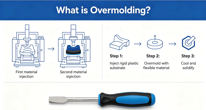
Overmolding is a molding process in which a second material is molded onto or around an existing substrate. The substrate may be a molded thermoplastic, a machined or stamped metal insert, an electronic assembly or another component that can tolerate the molding conditions. The second material may cover the entire substrate or only selected functional zones.
Many products use a rigid thermoplastic substrate with a softer thermoplastic elastomer (TPE) or thermoplastic polyurethane (TPU). Other combinations are possible, but each pair requires its own compatibility, temperature and application review. The interface may rely on chemical adhesion, mechanical retention or both.
Overmolding is commonly selected to create:
- Soft grips and ergonomic contact surfaces.
- Sealing lips, gaskets and local environmental barriers.
- Impact, vibration and abrasion protection.
- Electrical insulation or strain relief.
- Color contrast, branding zones and tactile features.
- A single integrated component that replaces a separately assembled pad, sleeve or gasket.
Overmolding does not automatically eliminate all primers, adhesives or mechanical features. Some material pairs bond directly under suitable molding conditions; others require a specially formulated overmold grade, surface preparation, a primer or a physical interlock.
Overmolding vs Two-Shot Molding vs Insert Molding
These terms describe related but different concepts.
- Overmolding is the broad result: a second material is molded over a substrate.
- Two-shot molding uses a machine and tool arrangement that molds the substrate and the second material in a coordinated cycle. A rotary platen, index plate, core-back movement or transfer system positions the first shot for the second injection.
- Insert overmolding places a separately manufactured substrate into the mold before the second material is injected. The insert may be loaded manually or by a robot.
- Insert molding is a wider category in which plastic is molded around a preformed insert, often metal. Not every insert-molded component uses a soft second material.
For a deeper comparison of molded plastic around preformed inserts, see the guide to insert injection molding.
When Does Overmolding Add Value?
Overmolding is most valuable when the second material performs a clear function and integration removes a separate manufacturing or assembly step. A soft grip can improve handling; a molded seal can reduce gasket placement; and a protective layer can isolate a vulnerable edge or cable exit.
The process is less attractive when demand is too low to support dedicated tooling, when the design is changing frequently or when the bond cannot survive the operating environment. A removable seal, replaceable wear pad or separately assembled component may be a better choice if serviceability is important.
Before choosing overmolding, define:
- The required function of the second material.
- Operating temperature and thermal cycling.
- Exposure to water, oils, cleaners, fuels, ultraviolet light or skin contact.
- Expected peel, shear, pull, torque, compression and fatigue loads.
- Regulatory, biocompatibility, flammability or food-contact requirements.
- Cosmetic limits for flow lines, knit lines, gate marks and color variation.
- Production quantity, automation target and acceptable tooling investment.
Standard Overmolding Workflow
1. Define Functional and Commercial Requirements
Start with the 3D CAD model, 2D drawing, target quantity and application requirements. Identify the surfaces that need soft touch, sealing or protection and the surfaces that must remain exposed. Mark critical interfaces, allowable witness lines, cosmetic zones and test requirements.
2. Select Candidate Material Grades
Choose the rigid substrate first and then identify overmold grades that are formulated for that specific substrate family. Review hardness, tensile and tear properties, compression set, chemical resistance, temperature range, color, regulatory status and supplier adhesion guidance. The manufacturing materials guide can help organize the initial selection, but the final pair must be confirmed at grade level.
3. Manufacture the Substrate
In two-shot molding, the first shot is produced in the same coordinated molding cell. In insert overmolding, substrates are molded, machined, stamped or otherwise manufactured separately. Substrate dimensions, flatness and locating features must be stable enough for repeatable loading into the overmold tool.
4. Prepare, Handle and Locate the Substrate
Dust, skin oil, mold release, condensation and other contamination can weaken adhesion. Stored inserts should be protected and handled consistently. Hygroscopic polymers must be dried according to the resin supplier’s instructions. Preheating can help some combinations but can harm others, so it must be based on grade-specific supplier data rather than applied as a universal rule.
The mold should locate the insert without over-constraining it. Supports must resist injection pressure without marking cosmetic surfaces or distorting thin sections.
5. Inject the Overmold Material
The second material enters through a gate, fills the overmold cavity, wets the substrate surface and flows through any retention features. Melt temperature, mold temperature, injection speed and pressure affect filling and interface quality. Venting at the end of fill allows displaced air and gases to escape.
6. Cool, Eject and Stabilize the Part
Cooling time must allow the part to eject without tearing, dragging or distorting the overmold. The tool should push on stable areas and avoid concentrated ejector loads on soft cosmetic surfaces. Some materials continue to shrink or condition after molding, so inspection timing should be agreed before capability data are collected.
7. Inspect and Validate
Inspection should cover substrate position, flash, short shots, surface condition, dimensions and bond performance. Functional products may also require leak testing, pull or peel testing, compression testing, thermal cycling, chemical exposure or life-cycle evaluation.
Overmolding Material Compatibility
Material compatibility is grade-specific. Labels such as ABS, PC, PP, PA, TPE, TPU and silicone describe material families, not guaranteed bonds. Additives, fillers, flame retardants, pigments, lubricants, recycled content and surface condition can change adhesion even when the polymer names appear compatible.
A material pair should therefore be selected using three levels of evidence:
- The overmold-material supplier recommends the exact substrate family or grade.
- The supplier’s processing window can be achieved without damaging or distorting the substrate.
- Molded test parts pass an adhesion test after conditioning for the real service environment.
The official Avient TPE Overmolding Guide discusses part design, mold design, processing, adhesion factors and troubleshooting. It also reinforces why a grade-specific guide is more useful than a universal compatibility chart.
Practical Starting Points for Common Substrates
- ABS, PC and PC/ABS: Many specialty TPE and TPU grades are formulated for these engineering plastics. Confirm the exact substrate and overmold grades, melt-temperature limits and cosmetic requirements.
- Polypropylene: Use an overmold grade designed to bond to PP. General-purpose TPEs that bond to polar engineering plastics may not bond reliably to PP.
- Polyamide or nylon: Select a nylon-bonding grade and follow drying requirements for both materials. Moisture condition, reinforcement and substrate temperature can affect the interface.
- Acetal, PBT and other difficult substrates: Direct adhesion may be limited. Specialized grades, primers, surface treatment or robust mechanical retention may be required.
- Metal: The polymer can be locked around holes, grooves, knurls or other retention features. If chemical adhesion or sealing is required, the surface condition and any primer or adhesive system must be validated.
- Liquid silicone rubber: Silicone overmolding uses different tooling, temperature control and bonding chemistry from conventional TPE overmolding. Do not assume that ordinary PP, ABS or TPU compatibility rules apply.
Do not publish a simple “easy bond” or “hard bond” matrix unless it names the exact commercial grades, preparation method, molding conditions and test method. A broad table can create false confidence and expensive production failures.
Chemical Adhesion and Mechanical Interlocking
Chemical adhesion forms when the overmold material wets and interacts with the substrate under suitable temperature, pressure and contact conditions. Good chemical adhesion can create a clean interface without visible retention holes, but it remains sensitive to material formulation, contamination and processing.
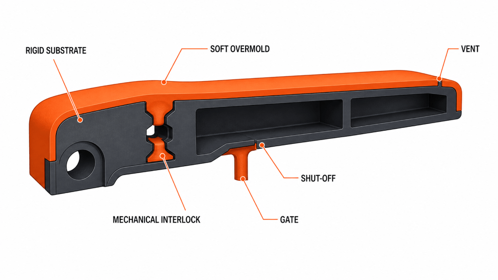
Mechanical interlocking uses geometry to prevent the overmold from peeling or sliding away. Common features include through-holes, slots, dovetails, undercut channels, wrap-around edges and local anchors. Mechanical retention is especially useful when:
- The material pair has limited or uncertain chemical adhesion.
- The interface will experience peeling rather than only compression.
- The product is exposed to fluids, heat, UV, cleaning or aging.
- The bond must remain functional even if surface adhesion is locally damaged.
- The overmold covers a metal insert or a low-surface-energy polymer.
Retention features must be filled and vented. A narrow hole that traps air or freezes before packing may look like an interlock in CAD but provide little production strength.
Overmolding Design Guidelines
Design a Stable Substrate
The first-shot or inserted component must withstand clamping, handling and the pressure and heat of the second shot. Thin unsupported walls can bow or collapse; tall flexible features can shift; and weak snap details can be damaged during loading. Add support close to overmold pressure zones without blocking material flow.
Set Overmold Thickness from Function and Flow
There is no universal 1.5-to-3-millimeter overmold rule. The workable thickness depends on material hardness, flow length, gate location, substrate temperature, texture, required cushioning, sealing compression and cosmetic expectations.
Use the material supplier’s flow-length and thickness guidance as a starting point. Maintain reasonably uniform sections, transition gradually between thicknesses and avoid isolated heavy masses that extend cooling time or create sink and distortion. Very thin sections may be practical with a suitable grade and short flow path, but they require coordinated part, gate and process design.
Control Shut-Offs and Flash
A shut-off is the tool interface that prevents the second material from flowing onto an exposed substrate surface. It must have sufficient steel support and a repeatable sealing condition. Place shut-offs away from critical sealing surfaces, tactile edges and prominent cosmetic zones where possible.
The substrate itself may form part of the shut-off. Its local thickness and position must therefore be consistent. Variation, burrs, sink or warpage at this interface can open a flash path even when the mold is correctly built.
Provide Draft and Release
Draft reduces drag during ejection. The required angle depends on texture depth, material hardness, draw length, steel condition and part geometry. Textured soft-touch surfaces generally need more draft than polished short faces. Confirm the value during tool DFM instead of applying one angle to every surface.
Avoid deep reverse features that can tear the elastomer during ejection unless a slide, lifter, collapsible core or intentional elastic release has been validated.
Position Gates for Balanced Filling
The gate should direct the overmold material across the substrate without jetting, displacing the insert or trapping air. Fill from thicker or well-supported regions toward vents when practical. Long thin flow paths may require multiple gates, a higher-flow grade or a different parting strategy.
Gate marks should be placed away from grip surfaces, sealing lips, datum features and high-visibility areas. If the gate is trimmed, define the permitted witness and whether secondary finishing is acceptable.
Vent the End of Fill
Trapped air can cause burns, short shots, poor surface replication and weak local adhesion. Vent the end of flow, weld-line regions and retention features. Vent geometry must suit the actual material; a vent that is too shallow may be ineffective, while an oversized vent can create flash.
Manage Texture, Parting Lines and Cosmetic Zones
Texture can improve grip and hide minor flow variation, but it also affects release and visual matching. Define the grain, gloss and approved appearance sample. Align parting lines and shut-offs with natural product edges when possible. Avoid asking the tool to create an invisible transition across a highly polished cosmetic surface without an agreed limit sample.
Separate Rigid and Soft-Material Tolerances
The rigid substrate controls many assembly datums, holes and structural interfaces. A soft overmold can compress, recover and deform during measurement. Apply tighter dimensional control only where function requires it and define the measuring method, fixture and conditioning state.
ISO 20457 covers tolerances and acceptance conditions for plastic molded parts, including thermoplastics and thermoplastic elastomers. It is a useful formal reference, but project tolerances still need to reflect the actual geometry, materials, tooling and measurement method.
Mold and Production Options
Separate-Tool Insert Overmolding
The substrate is produced in one operation and loaded into a second mold. This route can support lower or moderate volumes, mixed substrate processes and flexible loading, but it adds handling, storage and insert-location controls. Manual loading may be economical at lower volume; robotic loading improves consistency when production grows.
Two-Shot or Multi-Shot Molding
The substrate and overmold are produced in a coordinated molding cycle. This can reduce handling and contamination and improve repeatability at higher volume. The machine, tool and automation are more complex, so the production demand and design stability must justify the investment.
Core-Back, Rotary and Transfer Concepts
Some tools create the overmold cavity by retracting a core. Others rotate or transfer the first shot into a second cavity. The correct architecture depends on geometry, parting lines, production rate, machine capability and tool maintenance. It should be selected during DFM rather than specified only by a marketing label.
For projects moving from validation to repeat orders, rapid tooling can support design and process learning before a more automated production molding route is released.
Process Parameters That Affect Bonding and Appearance
Use the material suppliers’ data sheets as the starting process window. The important parameters interact, so one-variable fixes should be tested carefully and documented.
Drying and Material Handling
Hygroscopic resins must be dried to the supplier’s stated condition. Moisture can cause splay, bubbles, degradation and reduced properties. Regrind, colorant, additives and storage history should be controlled because they can change flow and bonding.
Substrate Surface and Temperature
The substrate should be clean and free of incompatible mold release. Its temperature affects wetting and the heat available at the interface. Immediate transfer from the first shot can improve some systems, but stored inserts require controlled protection and handling. Preheating must be validated for the exact pair.
Melt and Mold Temperature
An overmold melt that is too cool may freeze before it wets the substrate or fills thin regions. Excessive temperature can degrade the material, damage the substrate or extend the cycle. Mold temperature influences surface replication, flow, cooling and ejection.
Injection Speed, Pressure and Packing
The process must fill the overmold cavity before freeze-off without moving or damaging the substrate. Excessive pressure can force flash through shut-offs or deform a thin insert. Insufficient packing can leave sink, voids or incomplete retention features.
Cooling and Ejection
Cooling is based on the thickest relevant region, material properties and release behavior. There is no universal “slow first, fast later” cooling rule. Eject when the part can retain its shape and the soft material can release without tearing or dragging.
Common Overmolding Defects and Root Causes
Delamination or Weak Bonding
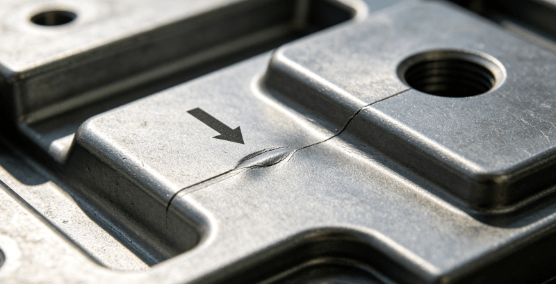
Possible causes include an incompatible grade pair, contamination, mold release, insufficient interface temperature, moisture, inadequate packing, poor surface contact or product loads that concentrate peel at an exposed edge.
Corrective action should start by confirming the exact materials and drying records, then reviewing surface handling, actual melt temperature, substrate temperature, gate location and bond-test failure mode. Add or improve mechanical retention if the service load cannot be supported by chemical adhesion alone.
Short Shots and Incomplete Interlocks
Possible causes include a frozen flow path, restrictive gate, trapped air, insufficient shot size, low melt or mold temperature, poor venting or excessive flow length for the selected grade.
Review the fill pattern, gate and vent locations before simply increasing pressure. If the geometry cannot fill robustly, a higher-flow grade, larger gate, shorter path or revised interlock may be required.
Flash at Shut-Offs
Flash can result from substrate variation, poor insert seating, damaged shut-off steel, insufficient tool support, excessive pressure, low material viscosity or mold deflection. Inspect both the tool and the substrate dimensions at the sealing interface.
Substrate Movement or Deformation
An insert may shift because the locator is weak, the filling pattern is unbalanced or the injection pressure acts on an unsupported surface. A thermoplastic substrate may also soften under second-shot conditions. Improve support, balance filling, reduce unsupported area or revise the material and process window.
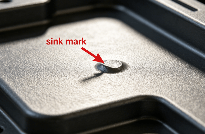
Sink, Voids and Distortion
Heavy overmold masses and abrupt thickness changes cool unevenly. Excess packing can also distort a thin substrate. Use more uniform sections, gradual transitions and realistic cooling, then verify the dimensions after the agreed conditioning period.
Flow Lines, Burns and Color Variation
These may indicate trapped air, temperature imbalance, material degradation, residence-time problems, inconsistent colorant mixing or a poorly placed gate. Cosmetic fixes should not be approved until bond strength and material properties remain acceptable.
Testing and Quality Control
Visual inspection alone cannot prove a reliable bond. The validation plan should reflect how the product is used and how the interface can fail.
Typical controls include:
- Verification of material lot, grade, drying and process records.
- Dimensional inspection of substrate location, critical rigid features and functional overmold geometry.
- Visual standards for flash, short shots, burns, contamination, color and texture.
- Peel, pull, shear, torque or push-out tests using a defined specimen and loading direction.
- Leak or pressure testing for integrated seals and fluid paths.
- Compression-set or sealing-force evaluation where the elastomer is compressed in service.
- Thermal cycling, heat aging, UV exposure and chemical immersion for the intended environment.
- Assembly and life-cycle testing under realistic product loads.
ASTM D429 provides standardized methods for evaluating rubber adhesion to rigid substrates, primarily metals. It may not apply directly to every TPE-on-plastic product, but it illustrates why the specimen, loading direction and test condition must be defined rather than reporting only that a part “passes adhesion.”
For production projects, align the drawing, control plan, sampling frequency, gauge method and acceptance criteria with the quality assurance and inspection system before tool release.
From Prototype to Production
The lowest-risk program validates function before investing in the final automation level.
DFM and Material Review
Confirm the substrate, overmold grade, interface, draft, shut-offs, gates, vents, locating and ejection. Identify any required mechanical retention and define the bond test.
Prototype or Material Coupon Testing
Prototype geometry can confirm grip, sealing and assembly, but a machined or bonded mock-up does not fully reproduce a molded interface. Use molded coupons or representative pilot parts to evaluate adhesion and environmental durability.
Tool Sampling and Process Development
Record actual melt temperature, mold temperature, injection settings, cooling and insert handling. Review the fill pattern and failure mode instead of accepting a cosmetically good part as proof of process capability.
Pilot Run and Capability Review
Run enough consecutive parts to expose variation in loading, heating, cooling and material handling. Measure critical characteristics and perform the agreed functional tests. Correct the process before high-volume production or automation is finalized.
Production Control
Freeze the approved material grades, color system, regrind rules, handling, machine setup and inspection plan. Changes to suppliers, formulations, additives or substrate preparation should trigger documented review and, when necessary, revalidation.
What Determines Overmolding Cost?
Overmolding cost is driven by the entire manufacturing route, not only the price of the soft material. Key factors include:
- One separate tool or an integrated two-shot tool.
- Manual, semi-automatic or robotic insert loading.
- Substrate production and dimensional consistency.
- Number of cavities and expected annual volume.
- Side actions, lifters, slides, core-back or rotating mechanisms.
- Overmold material grade, hardness, color and regulatory requirements.
- Insert cleaning, drying, preheating or surface preparation.
- Cycle time, cooling time and scrap risk.
- Cosmetic limits and flash-removal requirements.
- Adhesion, leak, dimensional and environmental testing.
A lower-cost quote that assumes generic TPE, no bond validation and a simple visual inspection is not equivalent to a controlled production route. Quote comparisons should use the same material grades, tool architecture, automation level and acceptance plan.
Quote-to-Parts Process
1. Upload the Design Package
Provide the 3D CAD model and a 2D drawing. STEP is suitable for geometry exchange, while PDF drawings can identify tolerances, datums, surface texture, cosmetic zones and test requirements.
2. Add Application Information
State the rigid substrate and preferred overmold material or performance requirements, expected annual quantity, target hardness, color, operating environment and regulatory needs.
3. Receive DFM and Process Recommendations
The engineering review should cover material pairing, interface design, mechanical interlocks, shut-offs, gates, vents, draft, insert location, ejection and inspection.
4. Confirm Tooling and Validation Plan
Agree on tool architecture, cavity count, steel, sampling, approved color and texture standards, bond test, dimensional report and functional testing.
5. Sample, Correct and Release Production
Review first samples against the drawing and validation plan. Correct material, tool or process issues before releasing repeat production.
Upload your CAD files with the material, quantity and application requirements to receive an overmolding DFM review and project quotation.
Frequently Asked Questions About Overmolding
Is Overmolding the Same as Two-Shot Molding?
No. Overmolding is the broader process of molding a second material onto a substrate. Two-shot molding is one automated method used to produce an overmolded part. Separate-tool insert overmolding is another method.
Does TPE Bond to Every Plastic?
No. Adhesion depends on the exact substrate and overmold grades, additives, surface condition and processing. Select a TPE or TPU formulated for the substrate and verify the bond with molded test parts.
What Is the Best Overmold Thickness?
There is no universal value. Thickness must support the required grip, seal, cushioning or protection while remaining fillable and stable. Use supplier flow guidance and confirm the geometry through DFM and sampling.
Do Overmolded Parts Need Mechanical Interlocks?
Not every part requires them, but interlocks are strongly recommended when chemical adhesion is uncertain, peel loads are high or the product faces heat, fluids, aging or repeated flexing.
Can Metal Be Overmolded?
Yes. Metal inserts can be overmolded for insulation, sealing, grip or protection. The design should include reliable locating and often holes, grooves, knurls or wrap-around geometry for retention. Surface preparation or primer may also be required.
Why Does an Overmold Delaminate?
Common causes include incompatible grades, contamination, mold release, moisture, low interface temperature, poor filling, insufficient contact or a design that exposes the bond edge to peel. Diagnose the failure mode before changing process settings.
How Should Overmold Adhesion Be Tested?
Use a repeatable test that represents the product load, such as peel, pull, shear, torque or push-out. Define specimen geometry, direction, speed, conditioning and acceptance criteria. Environmental aging should be included when relevant.
Can Overmolding Be Used for Low-Volume Production?
Yes, especially with a separate insert-overmolding tool and manual or semi-automatic loading. The economic choice depends on tool complexity, quantity, material, cycle time and validation requirements.
Request an Overmolding DFM Review
A reliable overmolded part begins with the correct grade pair, a protected interface and a tool that controls filling, venting, shut-offs and substrate position. Send SAMSHION your CAD model, drawing, material requirements, target quantity and application conditions. Our engineering team can review the design and recommend a practical prototype-to-production route.