CNC machined sleeves need to do more than accept a shaft or pin through the center. Their outside diameters may locate in another component, shoulders may establish an axial stop, and cross-holes may need to line up with a mating feature. A sleeve can meet its bore diameter limits yet fail an assembly requirement if the bore runs out relative to the locating outside diameter or a shoulder sits at the wrong distance.
At SAMSHION, the features we check on these parts include precision internal bores, fitting outside diameters, step lengths, bore runout relative to the outside diameter, and cross-hole positions. We select the machining route according to the drawing. This guide explains how those requirements fit together, what each inspection method establishes, and which details help a buyer obtain a useful manufacturing quote.
Identify the surfaces that locate the sleeve
A sleeve is a hollow component, but the drawing must explain which of its surfaces perform the locating function. The bore may receive a shaft, pin or another cylindrical part. An outside diameter may locate the sleeve in a housing. A shoulder or end face may control insertion depth. Flats, slots and transverse holes add further relationships that a diameter callout alone cannot describe.
Before discussing a tighter tolerance, identify the engagement length and contact surfaces. A short locating band and a long cylindrical seat do not behave identically in assembly. A relieved section may provide clearance rather than locate anything. Applying the same tight tolerance to every outside diameter can add machining and inspection work without improving the actual fit.
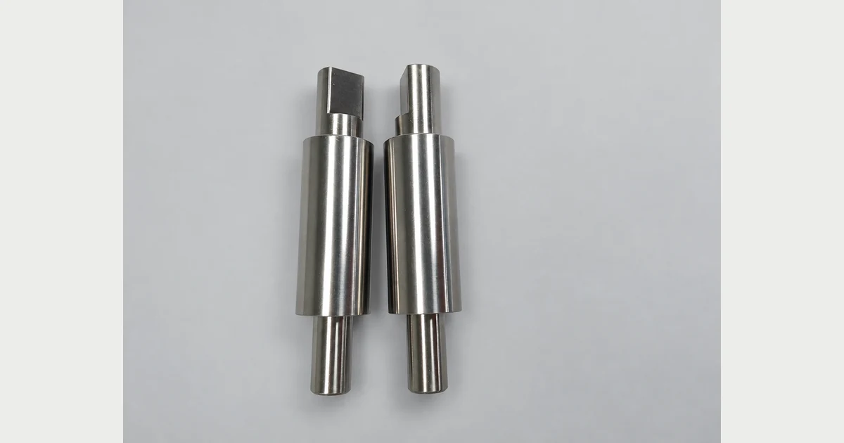
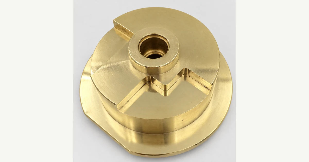
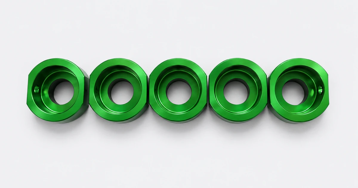
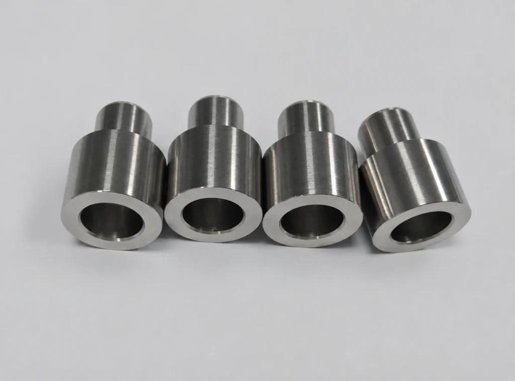
Precision machined sleeves also need to be distinguished from bearing products. A hollow shape does not establish a bearing function, wear rating or lubrication requirement. Those depend on the design and service conditions. The components photographed here illustrate sleeve geometry; their appearance does not establish an application or a measured tolerance.
Define bore fits using both mating components
A sleeve bore tolerance must be considered alongside the tolerance of the mating shaft or pin. The minimum diametral clearance is the smallest permitted bore minus the largest permitted shaft. The maximum clearance uses the largest permitted bore and smallest permitted shaft. Looking only at nominal diameters hides this range.
For a clearance fit, the permitted size ranges should provide the intended space between the parts. A transition fit can produce clearance or interference, depending on the actual sizes. An interference fit requires an assembly and structural review, especially where the sleeve wall is relatively flexible. The supplier should not choose a fit class merely because it is common on a different job.
The outside fit needs its own review. A sleeve may have one relationship to its mating shaft and another to the surrounding housing. Tightening the outside fit can affect the bore after assembly if the sleeve deforms. Where assembled bore performance matters, define whether acceptance applies before installation, after installation, or in both conditions. A loose-part dimensional report answers only the condition it actually measures.
If the mating part is a custom shaft, share its relevant tolerances with the sleeve drawing. Our CNC machined shafts guide discusses fitting diameters and stepped shaft features from the other side of the same interface.
Separate bore size from geometric accuracy
Precision sleeve bore machining starts with the size requirement, but size is only one part of the specification. A bore may also need a defined engagement length, an internal shoulder, a surface roughness requirement or a geometric relationship to another feature. These should be identified individually rather than summarized as a general request for high precision.
Roundness describes the shape of a circular section. Cylindricity concerns the cylindrical surface as a whole. Runout evaluates variation as the part rotates about a specified datum axis. These controls answer different questions, and a diameter check does not automatically verify all of them.
Consider a hypothetical sleeve with a shaft passing through two separated locating regions. The entrance diameter might accept a gauge while alignment or form farther into the part still causes difficulty. The drawing and inspection plan therefore need to identify the functional bore length and any additional geometry controls. A convenient measurement near the opening should not be treated as proof of the entire internal surface.
For stepped bores, specify each controlled diameter and the depth of its shoulder from a clear reference. Also identify the usable cylindrical length after allowing for chamfers, corner radii and tool access. A total bore depth can be correct while the actual locating length is too short.
Control fitting outside diameters and shoulder locations
The fitting outside diameter determines how the sleeve engages its surrounding component. At SAMSHION, we use a micrometer to check this diameter. The inspection plan should identify the relevant cylindrical band, because a reading on a clearance section does not verify a separate locating seat.
Where the tolerance and geometry require it, readings at different axial and angular positions can help reveal size variation. A single two-point reading is not a complete roundness evaluation. The measuring contact must also avoid chamfers, edge burrs and local interruptions that would make the reading unrepresentative.
Step lengths establish where shoulders and end faces sit along the part. We check these with a height gauge or CMM, according to the feature and drawing requirement. The reference face matters: two inspectors measuring from opposite ends can obtain different-looking results when the drawing controls the shoulder from only one end.
For stepped sleeve machining, review the tolerance chain between the locating face, shoulder and mating component. If one shoulder controls assembly depth, a direct dimension from the functional reference may communicate the requirement more clearly than several chained lengths. Any drawing change still needs the customer’s approval.
An internal corner deserves attention as well. A mating shoulder may interfere with an unspecified radius or burr before the intended faces make contact. Define the permitted radius, relief or edge condition where that contact affects seating. Do not assume a perfectly sharp internal corner can be produced by an ordinary turning tool.
Specify bore to OD runout against the correct datum
For sleeves that locate on an outside diameter, the relationship between that outside surface and the internal bore may be more important than either diameter alone. Bore to OD runout inspection evaluates the internal surface relative to the datum axis established by the specified external feature. At SAMSHION, we use a runout tester for the runout requirement.
The drawing must identify which outside diameter establishes the datum and which bore surface is controlled. A part with several external steps can offer several possible references, but they are not interchangeable. Supporting or aligning the sleeve on a convenient non-datum surface can answer a different question from the one on the drawing.
Circular runout evaluates variation at individual circular sections during rotation about the datum axis. Total runout evaluates variation over the controlled surface during that rotation. The drawing’s actual control determines the measurement coverage. One indicator reading at the mouth of a bore cannot be assumed to demonstrate total runout along its full length.
The test setup must reproduce the specified datum relationship, provide suitable access to the bore, and avoid distorting the part. Instrument resolution, alignment and repeatability need to suit the tolerance. The report should identify the controlled feature and reference rather than give an unexplained runout number.
Runout should not be casually renamed concentricity. The terms can describe different geometric requirements and evaluation methods. If a drawing uses a particular GD&T control, keep that control in the manufacturing discussion and report. The KEYENCE explanation of runout tolerance provides a concise distinction between circular and total runout.
Locate cross holes from the functional references
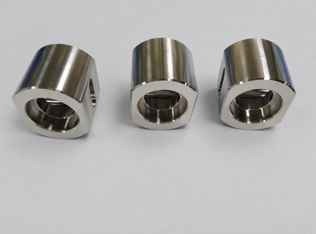
A transverse hole adds an axial position and an orientation relationship to an otherwise cylindrical component. Its diameter may be correct while its center lies at the wrong distance from a shoulder. If the hole has an angular relationship to a flat, slot or second hole, that relationship needs to be defined too.
We use CMM inspection for cross-hole positions. The program needs an alignment consistent with the drawing’s datums and enough accessible geometry to evaluate the required feature. Measuring the visible opening alone may not establish the full hole axis, particularly where the hole is deep, interrupted or difficult to probe.
Cross-hole position in a machined sleeve also depends on how the cylindrical features are referenced during subsequent machining. When turning and milling are separate operations, the handover between setups should preserve the intended references. Our guide to datum transfer across CNC setups explains why a correct local feature can still be misplaced relative to the rest of the component.
The intersection of a cross-hole and bore needs a separate edge review. A burr inside the bore can obstruct a mating part even when the measured hole positions are acceptable. Specify any required edge break and consider access for both deburring and inspection before production.
Select the bore machining route from the drawing
Custom machined sleeves do not all require the same sequence. Turning is suitable for many cylindrical features, while milling may be needed for flats, slots or transverse holes. Bore diameter, depth, accessibility, material condition and geometric requirements determine how the internal surface is produced and finished.
Drilling can create an initial hole. Boring or internal turning can establish or refine an accessible bore using a controlled cutting path. Reaming may be appropriate for finishing a prepared hole when the geometry and tolerance suit it. Specifying a reamer does not remove the need to review the preceding hole and its relationship to the locating surfaces.
These are process choices, not a promise that every sleeve is drilled, bored and reamed in that order. Some drawings justify additional finishing, while others can be met with a simpler route. If a particular process is mandatory for design or validation reasons, state it on the controlled specification. Otherwise, discuss the required result and let the manufacturing review determine a suitable route.
Deep or small bores can restrict tool diameter and increase tool reach. A longer, less rigid tool can be more sensitive to deflection and vibration. Chip evacuation and cutting access also become harder to manage. Sandvik Coromant’s boring application guidance emphasizes tool diameter and overhang as important planning factors.
Where practical, producing related internal and external features from a common setup can reduce errors introduced by reclamping. It does not guarantee compliance by itself. Subsequent operations, workholding and the final datum-based inspection still need to support the drawing requirement. Our hole tolerance machining guide gives further context for drilling, reaming and boring choices.
Plan workholding around the sleeve wall
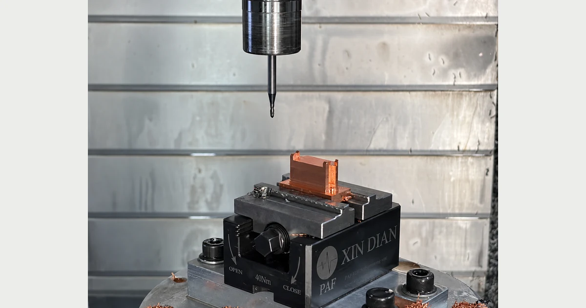
Thin wall sleeve machining requires attention to both the cut and the way the part is held. Radial clamping can temporarily change the shape of a flexible sleeve. Machining a bore while the part is distorted can leave a different free-state shape after release.
The relevant question is where the part has enough stiffness to support the machining load without damaging a functional surface. Depending on the design, possible approaches include distributing the contact, changing the gripping location, adjusting pressure or providing suitable support. The arrangement must leave access for machining and should not conceal the feature that later needs inspection.
An internal support is not automatically the right solution for every hollow part. It may restrict access or load a precision bore that should be protected. Similarly, reducing clamp pressure without considering cutting forces can make the setup insecure. Workholding must be assessed as a complete arrangement rather than a single pressure setting.
These considerations also apply to measurement. The drawing or agreed inspection plan should establish whether the dimension is evaluated free-state or under a specified restraint when that distinction matters.
Match each inspection method to its purpose
Sleeve bore inspection should be planned feature by feature. Our inspection methods are summarized below. The selected instrument still needs suitable range, access and capability for the actual tolerance.
What pin gauges establish
We use pin gauges to check sleeve bores. The selected gauge sizes and checking procedure should correspond to the bore requirement. For a GO and NO-GO approach, the acceptance rule and gauge tolerances must be established rather than simply treating any nearby pin as an acceptance gauge.
A pin entering a bore provides useful size-related evidence, but it does not supply a complete numeric map of the internal surface. It does not by itself certify bore runout, surface roughness or cross-hole position. Vermont Gage’s discussion of modified cylindrical gauges also illustrates why a round pin alone may miss certain out-of-round conditions.
Gauge length and access matter for stepped or blind bores. A pin may check only the region it can reach. Cleanliness, entry burrs and the checking technique can influence whether it enters. A failed check should therefore be investigated without forcing the gauge through the part or changing an edge merely to obtain a pass.
When the customer needs numeric bore results
A pin-gauge result and a measured bore diameter are different forms of evidence. If a customer requires actual bore values, a numeric profile or a formal report of form, that requirement should be shared during quotation. The measurement method must be selected for the bore geometry and tolerance; a pass result cannot be converted retrospectively into an exact diameter.
Likewise, a CMM report is useful only when it contains the required characteristics and uses an appropriate datum alignment. It should not replace a missing runout or size check merely because the equipment can measure many other features. Our CNC machining inspection guide explains how to connect inspection methods and reporting requirements.
Protect fit surfaces during finishing and handling
A precision sleeve can be difficult to assemble because of an edge burr, local damage or unsuitable surface condition even when basic dimensions appear acceptable. Review bore entries, cross-hole intersections and shoulder edges separately from the main diameter measurements.
A bore lead-in can help assembly, but an oversized chamfer reduces the usable locating length. Deburring must therefore preserve the specified edge geometry and nearby fitting surfaces. Our CNC deburring and edge inspection guide discusses how edge requirements should be communicated.
Surface roughness also needs its own callout where function requires it. A bright or reflective bore is not a measured roughness result. Neither a pin gauge nor an outside micrometer establishes a roughness parameter. Identify the controlled surface and required finish instead of relying on a photograph or a general instruction to polish the part.
If a drawing requires coating, plating or heat treatment, review when final dimensional acceptance will take place. Material addition, removal or distortion may affect the fit, depending on the process. The allowance and inspection sequence should be agreed for that job.
Provide a drawing that supports a sleeve machining quote
A useful RFQ defines the product and the evidence needed for acceptance. Send the controlled drawing with the CAD model, and identify which document governs tolerances and notes. For CNC sleeve components, include the following where applicable.
- The specified material grade and material condition, including any required certification.
- Bore diameters, tolerance limits, controlled depths and usable engagement lengths.
- Fitting outside diameters and the surfaces that locate the part in assembly.
- Shoulder and step lengths measured from clear functional references.
- The datum structure and actual bore runout control.
- Cross-hole diameters, positions and orientation requirements.
- Required edge conditions and surface roughness on functional surfaces.
- Any treatment requirements and the condition for final inspection.
- Quantity, inspection coverage, report format and any first-piece approval requirement.
Share the mating dimensions when the fit depends on another custom component. If only one bore section or outside band is critical, mark it clearly. This helps avoid interpreting a local fit requirement as a demand for identical precision over every surface.
Reporting requirements also affect the quote. Checking a bore with pin gauges, reporting numeric diameters at specified locations and evaluating a full geometric control are different tasks. Agree on which is required before production so that inspection time and equipment access are included in the plan.
Frequently asked questions about CNC machined sleeves
Can a sleeve pass a bore gauge check and still have excessive runout
Yes. Bore size and bore runout relative to a datum outside diameter are separate requirements. The gauge check establishes only the size-related condition covered by that gauge and procedure. Runout requires a suitable rotational measurement referenced to the specified datum.
Does every precision sleeve bore need reaming
No. The machining route depends on the drawing, material condition, bore geometry and required result. Reaming is one possible finishing operation for a prepared hole. It should not be specified automatically for every precision internal bore or treated as proof of alignment to an outside diameter.
Can the same tolerance be used for the inside and outside fits
The two interfaces should be reviewed separately. The bore mates with one component and the outside diameter with another. Their required clearance or interference, locating length and assembly conditions can differ. Using the same tolerance by habit does not establish the intended fit.
How are stepped sleeve lengths and transverse holes inspected
At SAMSHION, we use a height gauge or CMM for step lengths and a CMM for cross-hole positions. The reference face and datum alignment must match the drawing. The exact measurement coverage depends on the features and tolerances being accepted.
What should a precision sleeve inspection report include
Identify the drawing revision, part or lot, controlled feature, tolerance and inspection method. Record numeric measurements where that method supplies them and acceptance status where a gauge check is used. For runout and position, identify the datum references so the result can be interpreted correctly. Agree on the report scope and sample quantity before production.
Discuss the fit and inspection requirements before production
For CNC machined sleeves, start with the locating surfaces and then connect bore size, outside fit, step lengths, runout and cross-hole position to the assembly. Define the required evidence at the same time. A clear specification lets the machining route and inspection plan address the same functional requirement.
Send your drawing, CAD model, quantity and inspection requirements to SAMSHION for a machining review. Identify the critical bore and outside diameter, and share any mating-part tolerances that affect the fit.