Copper CNC machining can produce frames, pocketed components and mounting plates directly from solid stock. For the buyer, the important questions are which features control assembly, what surface condition is acceptable and how the finished part will be checked.
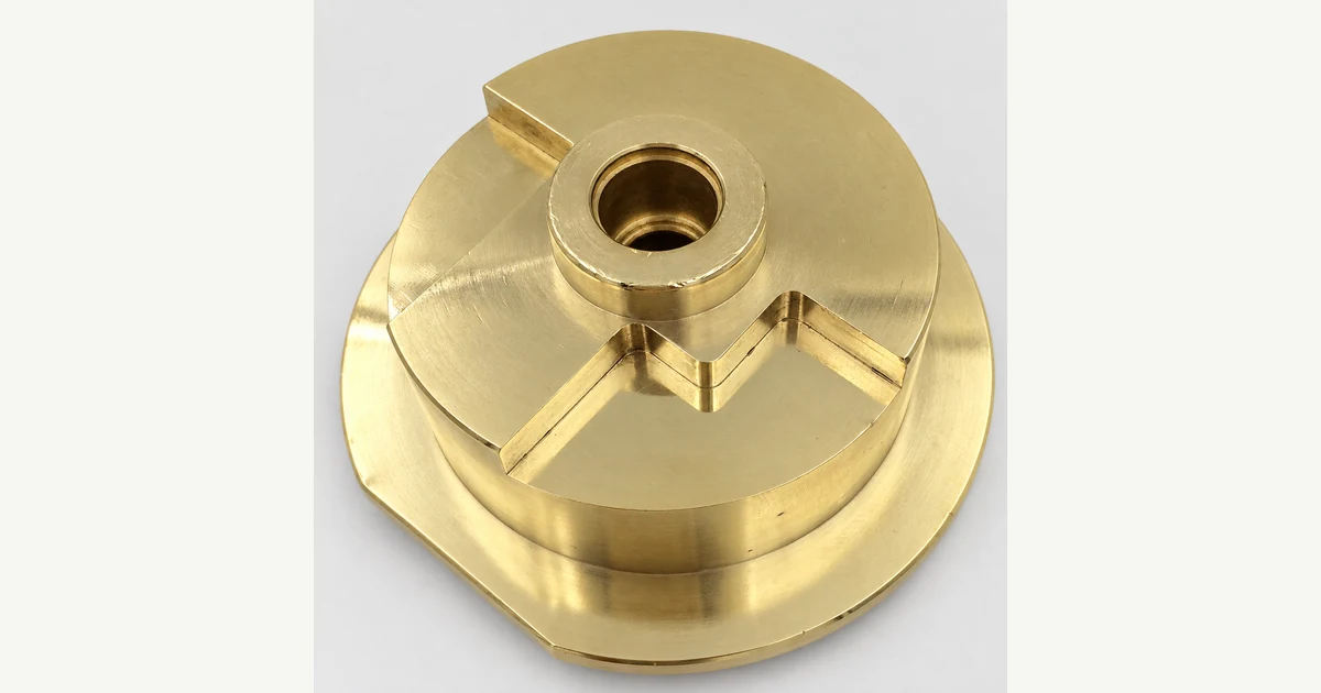
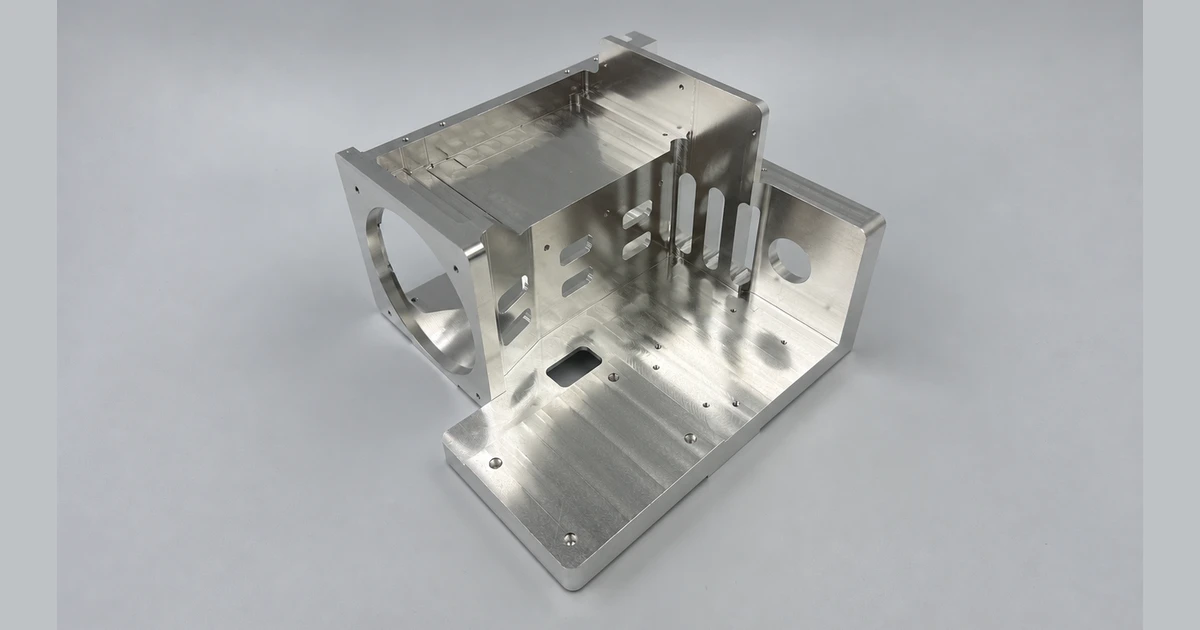
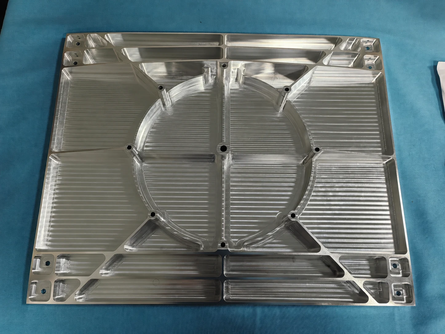
At SAMSHION, we regularly machine commonly available copper grades. The frame, plate and pocketed components illustrated in this article were CNC milled from solid material without bending, welding or other manufacturing processes. They are shown in their as-machined condition, without surface treatment. Their key requirements include hole diameter, hole position, slot width, thickness, mounting face flatness and protection against scratches or clamping marks.
Specify the copper grade and material condition
Copper is often selected for its electrical and thermal conductivity. However, the material description still needs to identify a grade and supply condition. The International Copper Association overview of copper and its alloys explains the range of properties within this material family. A general description such as red copper does not establish a purchasing specification.
For custom copper parts, provide the material designation, applicable standard and required temper or condition. If material documentation is required, agree on it before purchasing the stock. Any alternative material should be reviewed against the design requirements and approved before use.
Brass is a family of copper-zinc alloys, so a brass designation should not be treated as interchangeable with a copper grade. Our brass CNC machining guide covers that separate material group. Neither the color nor the brightness of a finished component is sufficient to verify its grade.
Copper CNC milling from solid stock
Copper CNC milling removes material to create the external profile and internal features. An open frame can retain integral corner pads, while a pocketed component can include a floor, raised mounting areas and slots in one piece. These shapes do not necessarily require fabrication or joining.
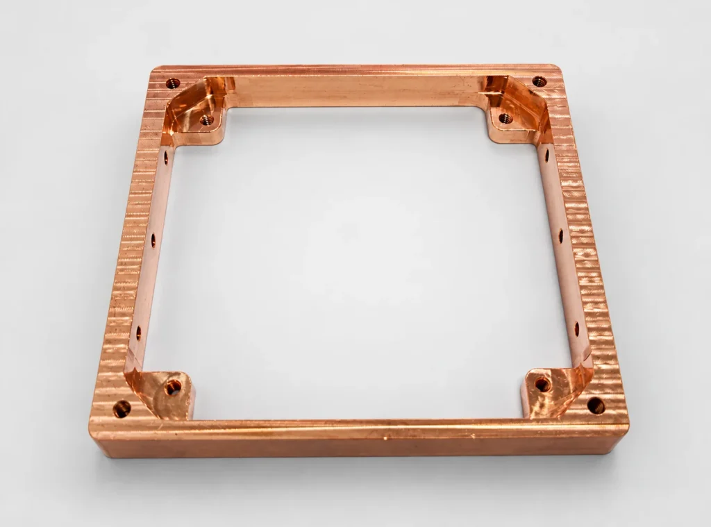
During drawing review, identify which faces locate the part in the assembly and which holes or slots relate to those faces. This helps establish the machining references and the inspection alignment. If a feature must be reached from another side, the process plan also needs to preserve those relationships when the part is repositioned.
Tool access matters around pocket walls, recessed pads and narrow openings. Allow an internal corner radius where the design permits it, and make the required pocket depth clear. A smaller cutter may reach a tighter corner, but its usable length and stiffness still need review. The CNC milling service page provides the broader process context.
These are routine planning considerations. A frame or pocket alone does not mean a copper job is unusually difficult or needs an additional manufacturing process.
Define hole size and hole position separately
A hole diameter controls the opening available to a mating feature. Hole position controls where that opening sits relative to other features or drawing references. Both may matter even when the same tool creates the hole.
For example, an acceptable clearance diameter does not establish that a mounting pattern aligns with the mating part. Conversely, the correct pattern location does not establish the required fit in an individual bore. Specify each requirement that affects assembly rather than applying the same tight tolerance to every dimension.
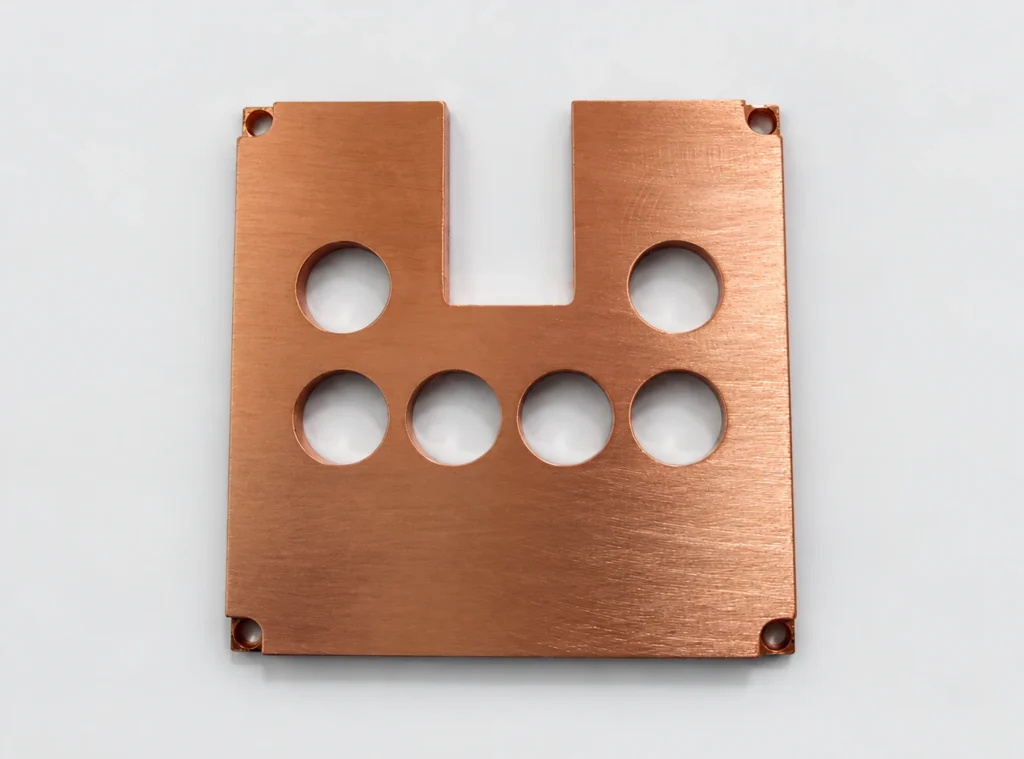
Identify through holes, blind holes, counterbores and threaded holes clearly. Thread callouts should include the thread specification and required usable depth. Where a bore has a fitting function, provide the size limits and any additional form or surface requirements.
Inspection must answer the corresponding question. Properly selected pin or plug gauges can provide size-limit checks on suitable accessible holes. An internal measuring instrument can provide numerical bore measurements. Hole positions require a measurement method tied to the drawing references, such as an appropriately programmed coordinate measuring machine, or CMM. A single pin check does not verify the location of a hole pattern. The hole tolerance guide explains size and location requirements in more detail.
Make slot and pocket requirements unambiguous
A slot may provide clearance, adjustment or a locating function. State its width, length, depth and location as needed for that function. For an open notch, show whether the end geometry and internal corner radii are controlled. For a through slot, clarify any edge break needed on both sides.
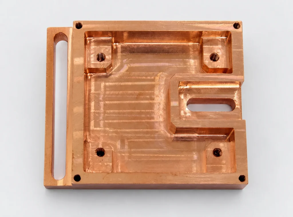
Pocketed copper parts also need a clear definition of thickness. Overall stock thickness, pocket depth and the remaining floor thickness describe different characteristics. If the floor thickness is critical, dimension it directly or define an unambiguous dimensioning scheme. The same principle applies to a raised pad that must sit at a controlled height relative to a mounting face.
A photograph can help explain the shape, but it cannot establish which of these dimensions controls the design. Keep the controlled drawing consistent with the 3D model, especially when a slot or pad changes between revisions.
Control thickness and mounting face flatness
Thickness describes the distance between opposing surfaces under the applicable drawing definition. Flatness describes the form of an individual surface. A thickness measurement at a few accessible points does not, by itself, establish the flatness of a mounting face.
For a copper frame, identify whether the assembly contacts the continuous perimeter or only selected pads. For a pocketed part, identify which face actually seats against the mating component. Apply the required control to the intended surface. If separate pads must act as one mounting interface, define their relationship explicitly with an appropriate drawing specification.
If the design also requires one face to be oriented relative to another, consider the relevant orientation control. Flatness alone does not control that relationship. Our flatness and parallelism guide explains the distinction.
Inspection planning should cover the relevant area of the surface and use support that does not force the component into an artificial shape. A gap at one point between a part and a platform may help describe local lift, but it is not automatically a flatness result for the specified face. Agree on any required restrained measurement condition before acceptance testing.
Define copper surface quality before machining
As-machined copper parts can retain visible cutting paths and changes in reflection between faces. These appearances should be assessed against the required surface finish and any agreed cosmetic criteria. A bright photograph does not demonstrate a particular roughness value, and a visible tool path does not by itself prove that a dimensional requirement has failed.
For general process planning, copper’s ductility and tendency to adhere to a cutting edge deserve attention. The Copper Development Association machining discussion describes how tool geometry, lubrication and chip flow affect copper surface finish. Tool selection and cutting conditions should suit the specified grade and the feature being machined; a universal speed and feed table cannot establish the correct settings for every job.
Separate the following drawing requirements where they matter:
- Functional surface requirements, such as specified roughness on a fitting or mounting face.
- Cosmetic requirements, including the faces on which scratches or clamping impressions are restricted.
- Edge requirements, including burr removal and permitted chamfers or radii.
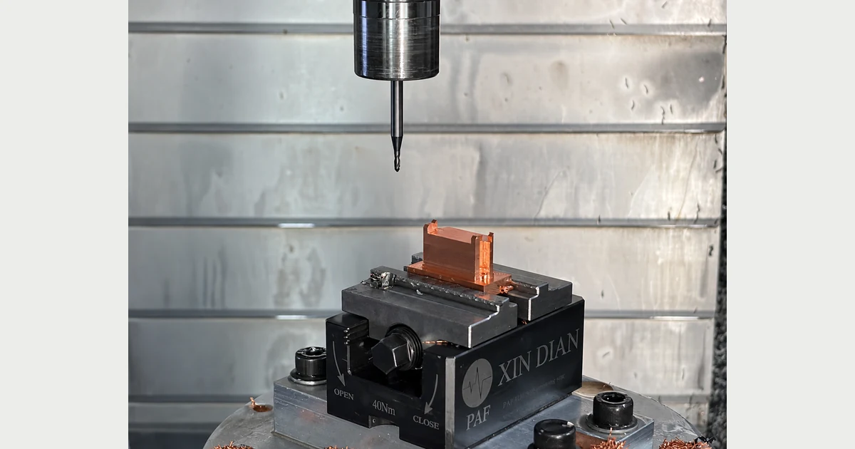
Clamping and handling should be planned around the identified surfaces. Clean contact faces, suitable protective pads or soft jaws, and sufficient support can help limit impressions. The setup must still hold the part securely. During storage and transport, separate parts and use suitable protective material to limit contact damage. These measures should be selected for the component, including any cleanliness requirement on contact surfaces.
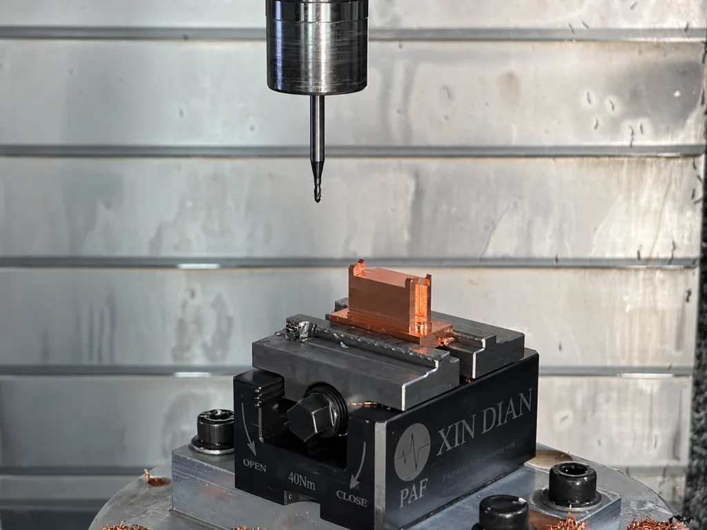
Do not remove a scratch by uncontrolled polishing on a dimensionally critical face. Rework can change thickness, edge geometry or surface form and needs an agreed method followed by the relevant checks. The surface roughness and dimensional tolerance guide covers why these requirements need separate evaluation.
Match inspection to each copper part feature
An inspection plan should state the characteristic, drawing requirement, method and reporting format. The following are method options to review for the actual geometry and tolerance, rather than a prescribed instrument list for every copper job.
A CMM can evaluate accessible geometric features, but its usefulness depends on the probing strategy, alignment and evaluation. Other instruments may be more appropriate for a particular size check. Surface roughness requires a suitable surface measurement method, while cosmetic inspection needs its own acceptance criteria.
If a report is required, state whether it should contain measured values, pass or fail results, or a first article layout. A product photograph is useful for identification and communication; it does not replace dimensional inspection records. See our CNC machining inspection guide for report planning.
What to include in a copper machining enquiry
Send a current 3D model and controlled drawing together. Include the following information where it applies:
- Copper grade, applicable material standard and supply condition.
- Quantity and required delivery date.
- Critical hole sizes, positions, slots and thicknesses.
- Mounting references and geometric tolerances.
- Surface roughness, cosmetic faces and permitted edge breaks.
- As-machined delivery or a specified subsequent finish.
- Material documentation, inspection report and packaging requirements.
If a requirement is still open, identify it before quotation. This allows the material, machining plan and acceptance method to be reviewed together. Tighten the characteristics that affect function; a blanket tolerance on every feature can add work without addressing the assembly requirement.
Frequently asked questions
Can a copper frame be milled in one piece
Yes. The copper frame illustrated here was milled from solid material. Whether that route is appropriate for another design depends on its geometry, material, quantity and drawing requirements.
Do copper CNC parts always need surface treatment
No. The illustrated finished components are shown without surface treatment. Whether another part should be supplied as-machined, plated or otherwise finished depends on its service and appearance requirements. Specify the delivered condition in the enquiry.
Can copper and brass use the same material callout
No. A copper grade and a brass grade identify different materials. Confirm any proposed substitution against the design requirements before manufacturing.
What tolerance can be quoted for copper parts
Tolerance feasibility requires review of the feature size, geometry, material condition, tool access and measurement method. Provide the actual drawing requirements so the supplier can assess the relevant features rather than promise one tolerance for the whole part.
Discuss your copper CNC machining requirements
SAMSHION machines custom copper components from commonly available grades. Send your model, drawing, material specification and delivery requirements for review. Identifying the fitting features, mounting faces and protected surfaces early helps define the machining and inspection work needed for your part.