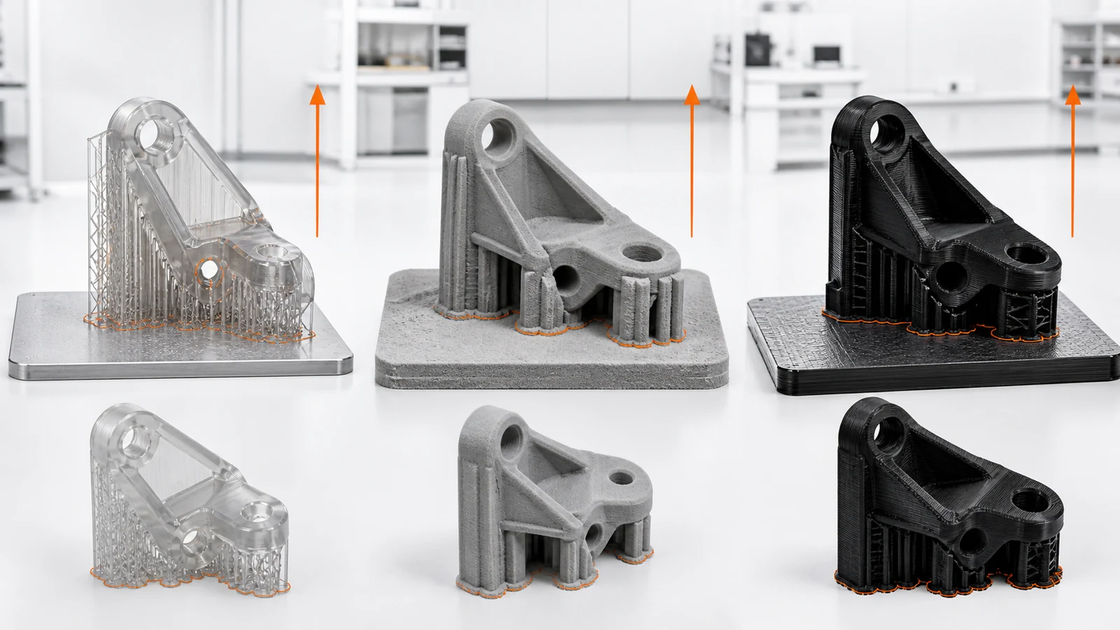
A CAD model can usually be placed in many directions, but the printed result is not orientation-neutral. Layer interfaces, support contact, heat flow, recoating, drainage, trapped powder or resin and post-processing access all change with the build direction.
The correct orientation is selected from the required function and the chosen process. Strength direction, accuracy, cosmetic faces, hole quality, support removal, build height, packing density and inspection datums must be ranked instead of optimized one at a time.
Scope, Search Intent and Technical Boundary
This article begins after the additive process and material family have been selected. It explains how build orientation changes load direction, support contact, drainage or powder removal, build height, distortion, feature quality and the final inspection state. For one process-specific reference, consult the Stratasys guide to orienting parts for DLP printing.
It is not a general explanation of SLA, SLS, FDM, MJF or metal printing. Process capability and quotation belong on SAMSHION’s 3D printing services page, while cross-process prototype selection belongs on the rapid prototyping services page. This article addresses the orientation decision within the selected route.
Key Takeaways
- Choose orientation only after selecting the additive process and material.
- Align critical load paths with the process’s qualified property data.
- Keep support evidence away from controlled cosmetic and mating surfaces.
- Orient holes and thin features for the actual process limits.
- Inspect the delivered part in its post-processed condition.
Why Orientation Is a Process Variable
Orientation changes the relationship between geometry and layer formation, making it a manufacturing parameter rather than a display preference. Choose the additive route first through the 3D printing services page, then use this article to evaluate orientation within that selected process.
Balance Strength and Directional Properties
Layer-based processes can produce different properties by direction, so the real load case must be compared with qualified material and process data. For broader geometry review across manufacturing routes, use the design for manufacturability guide; this section remains limited to the orientation and load-direction tradeoff.
Place Supports and Protect Critical Surfaces
Support requirements depend on technology, but contact removal can damage finish, edges and dimensions.
Control Accuracy, Distortion and Feature Quality
Build height, thermal accumulation, peel forces, scan strategy and feature direction can change form and local detail. For the corresponding manufacturing decision and capability context, consult SAMSHION’s quality assurance.
Plan Post-Processing and Inspection
Cleaning, depowdering, UV or thermal cure, support removal, machining and coating all affect the final acceptance state. For the corresponding manufacturing decision and capability context, consult SAMSHION’s surface finishing services.
Engineering Variables to Confirm Before Quotation
Printing technology and exact material system
Confirm printing technology and exact material system before quotation. Evaluate it against load direction, supported surfaces, distortion, trapped material and post-processed datums. Record the agreed value, part condition and acceptance stage on the controlled drawing or DFM record so build preparation, printing, support removal, post-processing and inspection use the same requirement.
Build direction relative to functional loads
Confirm build direction relative to functional loads before quotation. Evaluate it against load direction, supported surfaces, distortion, trapped material and post-processed datums. Record the agreed value, part condition and acceptance stage on the controlled drawing or DFM record so build preparation, printing, support removal, post-processing and inspection use the same requirement.
Support, drainage and powder-removal access
Confirm support, drainage and powder-removal access before quotation. Evaluate it against load direction, supported surfaces, distortion, trapped material and post-processed datums. Record the agreed value, part condition and acceptance stage on the controlled drawing or DFM record so build preparation, printing, support removal, post-processing and inspection use the same requirement.
Critical holes, mating faces and cosmetic zones
Confirm critical holes, mating faces and cosmetic zones before quotation. Evaluate it against load direction, supported surfaces, distortion, trapped material and post-processed datums. Record the agreed value, part condition and acceptance stage on the controlled drawing or DFM record so build preparation, printing, support removal, post-processing and inspection use the same requirement.
Thermal mass, cross-section changes and build height
Confirm thermal mass, cross-section changes and build height before quotation. Evaluate it against load direction, supported surfaces, distortion, trapped material and post-processed datums. Record the agreed value, part condition and acceptance stage on the controlled drawing or DFM record so build preparation, printing, support removal, post-processing and inspection use the same requirement.
Post-processing and final inspection datum
Confirm post-processing and final inspection datum before quotation. Evaluate it against load direction, supported surfaces, distortion, trapped material and post-processed datums. Record the agreed value, part condition and acceptance stage on the controlled drawing or DFM record so build preparation, printing, support removal, post-processing and inspection use the same requirement.
Failure Modes and Root-Cause Diagnosis
A load-bearing feature splits along weak layer interfaces
When a load-bearing feature splits along weak layer interfaces, inspect layer direction, support contact, heat accumulation, drainage, powder removal and post-process clamping. Compare the affected part with a controlled reference and change one suspected variable at a time. Retain the failed part, process record and measurement evidence until the root cause is confirmed.
Support scars damage a sealing or cosmetic face
When support scars damage a sealing or cosmetic face, inspect layer direction, support contact, heat accumulation, drainage, powder removal and post-process clamping. Compare the affected part with a controlled reference and change one suspected variable at a time. Retain the failed part, process record and measurement evidence until the root cause is confirmed.
A tall part bows or twists during building or cure
When a tall part bows or twists during building or cure, inspect layer direction, support contact, heat accumulation, drainage, powder removal and post-process clamping. Compare the affected part with a controlled reference and change one suspected variable at a time. Retain the failed part, process record and measurement evidence until the root cause is confirmed.
Trapped resin or powder remains inside an enclosed passage
When trapped resin or powder remains inside an enclosed passage, inspect layer direction, support contact, heat accumulation, drainage, powder removal and post-process clamping. Compare the affected part with a controlled reference and change one suspected variable at a time. Retain the failed part, process record and measurement evidence until the root cause is confirmed.
Process Controls for a Repeatable Result
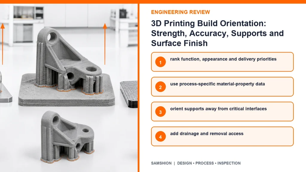
Rank function, appearance and delivery priorities
Implement rank function, appearance and delivery priorities as a documented process control. Record machine, material lot, orientation file, support strategy, build position, cure or heat treatment and post-processing route. Verify the control on the first article, then define the check frequency and reaction limit for repeat production.
Use process-specific material-property data
Implement use process-specific material-property data as a documented process control. Record machine, material lot, orientation file, support strategy, build position, cure or heat treatment and post-processing route. Verify the control on the first article, then define the check frequency and reaction limit for repeat production.
Orient supports away from critical interfaces
Implement orient supports away from critical interfaces as a documented process control. Record machine, material lot, orientation file, support strategy, build position, cure or heat treatment and post-processing route. Verify the control on the first article, then define the check frequency and reaction limit for repeat production.
Add drainage and removal access
Implement add drainage and removal access as a documented process control. Record machine, material lot, orientation file, support strategy, build position, cure or heat treatment and post-processing route. Verify the control on the first article, then define the check frequency and reaction limit for repeat production.
Reserve machining stock on qualified surfaces
Implement reserve machining stock on qualified surfaces as a documented process control. Record machine, material lot, orientation file, support strategy, build position, cure or heat treatment and post-processing route. Verify the control on the first article, then define the check frequency and reaction limit for repeat production.
Validate orientation with representative builds and inspection
Implement validate orientation with representative builds and inspection as a documented process control. Record machine, material lot, orientation file, support strategy, build position, cure or heat treatment and post-processing route. Verify the control on the first article, then define the check frequency and reaction limit for repeat production.
Inspection Strategy and Acceptance Evidence
Dimensions relative to functional datums
Evaluate dimensions relative to functional datums using datum-based dimensional inspection, profile or warpage checks, controlled surface review, channel clearance and functional load testing. State the part condition, datum or reference, acceptance limit and actual result. Keep the result traceable to build ID, machine, material batch, orientation revision and post-process lot.
Warpage, curl and overall profile
Evaluate warpage, curl and overall profile using datum-based dimensional inspection, profile or warpage checks, controlled surface review, channel clearance and functional load testing. State the part condition, datum or reference, acceptance limit and actual result. Keep the result traceable to build ID, machine, material batch, orientation revision and post-process lot.
Support-removal and downward-surface condition
Evaluate support-removal and downward-surface condition using datum-based dimensional inspection, profile or warpage checks, controlled surface review, channel clearance and functional load testing. State the part condition, datum or reference, acceptance limit and actual result. Keep the result traceable to build ID, machine, material batch, orientation revision and post-process lot.
Hole and channel clearance
Evaluate hole and channel clearance using datum-based dimensional inspection, profile or warpage checks, controlled surface review, channel clearance and functional load testing. State the part condition, datum or reference, acceptance limit and actual result. Keep the result traceable to build ID, machine, material batch, orientation revision and post-process lot.
Mechanical evidence in the required load direction when specified
Evaluate mechanical evidence in the required load direction when specified using datum-based dimensional inspection, profile or warpage checks, controlled surface review, channel clearance and functional load testing. State the part condition, datum or reference, acceptance limit and actual result. Keep the result traceable to build ID, machine, material batch, orientation revision and post-process lot.
Cost, Lead Time and Quotation Transparency
Build height and machine occupancy
Treat build height and machine occupancy as a separate quotation driver when it changes build height, platform occupancy, support material, removal labor, secondary machining or repeat builds. State what is included, the assumed acceptance evidence and which design or process change would require requotation.
Support material and removal labor
Treat support material and removal labor as a separate quotation driver when it changes build height, platform occupancy, support material, removal labor, secondary machining or repeat builds. State what is included, the assumed acceptance evidence and which design or process change would require requotation.
Part nesting and packing density
Treat part nesting and packing density as a separate quotation driver when it changes build height, platform occupancy, support material, removal labor, secondary machining or repeat builds. State what is included, the assumed acceptance evidence and which design or process change would require requotation.
Secondary machining, coating and inspection
Treat secondary machining, coating and inspection as a separate quotation driver when it changes build height, platform occupancy, support material, removal labor, secondary machining or repeat builds. State what is included, the assumed acceptance evidence and which design or process change would require requotation.
A Practical Engineering Review Sequence
Rank the part requirements before choosing orientation: load path, critical datums, internal channels, cosmetic faces, tolerance and delivery. A single orientation rarely optimizes every requirement at once.
Review layer direction, down-facing surfaces, support access, drainage or powder removal and thermal mass together. Protect critical faces and add machining stock only where the final datum or finish justifies it.
Approve the orientation with a traceable representative build. Inspect the part after all specified curing, heat treatment and support removal, then record the orientation and post-process route with the accepted result.
RFQ and DFM Checklist
- 3D model and drawing with functional datums and critical dimensions
- Printing technology and material, or required end-use properties
- Primary load direction, load case and permitted anisotropy
- Cosmetic faces, support-prohibited zones and required surface finish
- Internal channels, drainage, powder-removal and trapped-volume requirements
- Post-cure, heat treatment, coating and secondary-machining requirements
- Quantity, inspection level and representative functional test
Frequently Asked Questions
Is the strongest orientation always best?
Not necessarily; accuracy, supports, surface finish, build risk and cost also matter. Final acceptance depends on the stated datum, delivered state and inspection approach.
Do SLS or MJF parts need supports?
They are supported by powder, but orientation still affects packing, thermal behavior, surface and feature quality. Final acceptance depends on the stated datum, delivered state and inspection approach.
Can supports be placed on cosmetic surfaces?
They can, but removal evidence must meet the approved appearance standard. The general rule does not replace a feasibility review of the complete geometry and acceptance method.
Should holes be printed horizontally or vertically?
The answer depends on process, diameter, accuracy and whether post-machining is available. Confirm the project-specific answer from the controlled drawing and the actual material condition.
Does orientation affect quoted price?
Yes, through build height, packing, support volume, risk and post-processing effort. Confirm the project-specific answer from the controlled drawing and the actual material condition.
Get an Engineering Review
Upload the native CAD model, controlled drawing, material specification, quantity and required finish for a project-specific review of 3D printing build orientation.
For a review of 3D printing build orientation, send the native CAD model, controlled drawing, material specification, quantity, finishing route and required acceptance records. SAMSHION’s engineering team can return project-specific DFM questions and documented quotation assumptions before production begins. When the model and drawing are ready, use upload your 3D model and include the material, quantity, finish and inspection requirements.