
Sheet Metal Bending Services for Custom Parts
Turn flat laser-cut blanks into accurate brackets, channels, panels and enclosures with CNC press brake bending. SAMSHION supports prototypes, low-volume batches and repeat production with DFM feedback, bend-sequence planning, secondary fabrication and inspection based on your drawings.
- Steel, stainless steel, aluminum and approved copper alloys
- Simple flanges, multi-bend brackets, channels and enclosure panels
- Laser cutting, hardware installation, welding and finishing available
- Critical dimensions and angles reviewed before production
Custom CNC Bending from Prototype to Production
CNC press brake bending uses a controlled punch, die and backgauge to form a flat sheet-metal blank along programmed bend lines. The process is widely used for components that need flanges, returns, channels, mounting faces or enclosure geometry without the dedicated forming tool required by stamping.
Metal bending is one stage within our broader sheet metal fabrication services. A complete component may move from laser cutting to deburring, bending, hardware installation, welding, surface finishing and final inspection. Reviewing the entire route before cutting helps avoid interference, distorted holes and tolerance stack-up later in production.
For quotation, send a folded STEP model and a 2D drawing. Include the material grade and temper, sheet thickness, bend angles, inside radii, critical dimensions, finish, cosmetic surfaces, hardware, welding notes and required inspection records. A flat DXF can also be supplied when the developed blank has already been approved.
Why Choose SAMSHION for Sheet Metal Bending?
DFM Review Before Material Is Cut
We review flange lengths, bend radii, hole-to-bend distance, reliefs, grain direction, tooling access and bend sequence before releasing the flat blank. This catches problems while changes are still inexpensive.
Integrated Cutting, Forming and Assembly
The flat pattern, bend route, hardware, weld joints and coating requirements are planned together. One coordinated route reduces handoff errors and helps critical interfaces remain consistent.
Flexible Quantities
Standard press brake tooling supports prototypes and changing designs without a dedicated production die for every profile. Special tooling may still be required for narrow channels, offset forms, hemmed edges or restricted-access geometry.
Inspection Focused on Functional Dimensions
Angles, flange lengths, hole locations and overall formed dimensions are checked according to the drawing and manufacturing risk. Additional reports can be defined during quotation.
What Is CNC Press Brake Bending?
A CNC press brake forms sheet metal by driving a punch toward a matching die while a programmable backgauge positions the blank. The formed angle is influenced by punch travel, tooling geometry, material strength, thickness, rolling direction and springback. The machine program controls the sequence and positions, but experienced process planning is still required for tooling access, safe handling and dimensional control.
Air bending is the most flexible method for many custom parts because the final angle is controlled mainly by punch penetration into the V-die. Bottoming, coining, hemming, offset forming or special tooling may be considered for selected geometries, but availability and suitability must be confirmed for the actual part. Roll bending and stamping are separate forming processes and should not be presented as standard press brake capabilities unless SAMSHION has verified equipment for them.
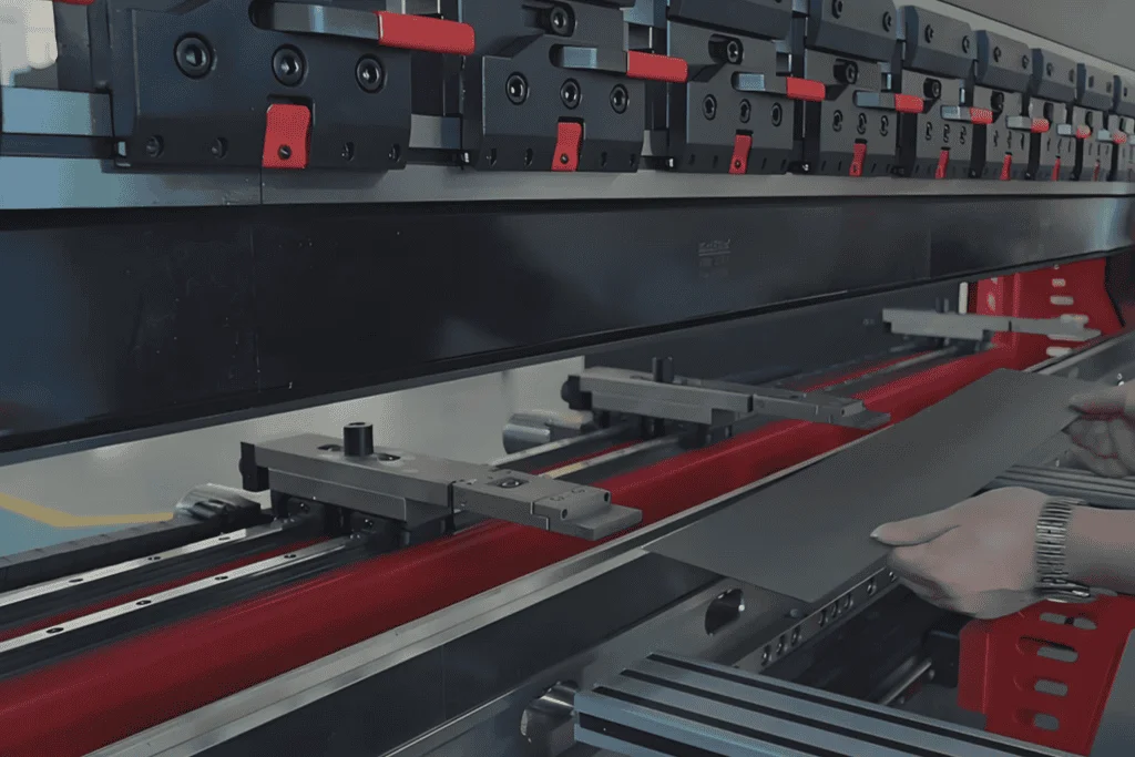
Our CNC Bending Capabilities
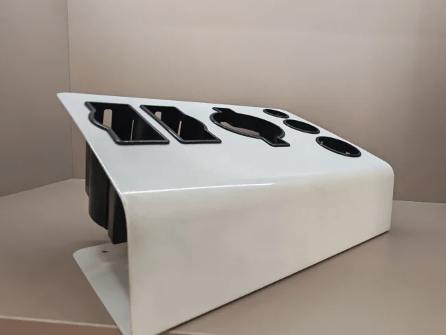
How the Sheet Metal Bending Process Works
File and Drawing Review
The engineer checks material, thickness, bend angles, inside radii, critical dimensions, cosmetic faces and the relationship between the folded model and flat blank.
Bend Allowance and Flat Pattern Review
The developed blank is reviewed using the intended bend radius, tooling and material behavior. K-factor or bend deduction values may be adjusted from validated shop data.
Tooling and Sequence Planning
Punches, dies, backgauge positions and the bend order are selected to avoid flange collision and restricted access.
First-Off Forming
A first part or test coupon is formed. Critical angles and dimensions are measured, and springback compensation is adjusted when required.
Production Bending
Approved settings are used for the order. Operators monitor material variation, orientation, handling and features that can distort near bend zones.
Secondary Operations and Inspection
Parts continue through hardware, welding, finishing or assembly, then receive the drawing-based checks agreed for the project.
Types of Press Brake Bends
Air Bending
The sheet contacts the punch tip and die shoulders without fully conforming to the die. One tool set can form a range of angles, making air bending suitable for many prototypes and custom production parts.
Bottom Bending
The sheet is formed closer to the die angle to reduce springback variation. Tool angle, material condition and tonnage must be matched to the application.
Offset and Joggle Bending
Two nearby bends create a stepped surface for clearance, overlap or mounting. Standard or special offset tooling may be required depending on step depth and material.
Hemming and Edge Forming
An edge is folded back to improve stiffness, appearance or handling safety. Hem geometry, material ductility and the final gap must be reviewed before production.
Channel and Box Bending
Multiple bends create U-channels, trays and enclosure sections. Gooseneck or segmented tooling may be needed to avoid interference on later bends.
Materials for Sheet Metal Bending
Material grade, temper and rolling direction affect bend radius, springback, surface condition and cracking risk. Review our manufacturing materials guide for broader comparisons, then specify the exact material on the drawing.
Carbon and Mild Steel
Common for structural brackets, frames, chassis and general enclosures. Formability depends on grade, thickness and strength condition.
Stainless Steel
Used for corrosion-resistant equipment, food-contact components and clean assemblies. Higher strength and springback usually require larger radii or additional compensation compared with mild steel.
Aluminum
5052 is commonly selected for formed enclosures and brackets. 6061-T6 is less forgiving in tight bends and normally requires a larger radius and careful grain orientation.
Galvanized or Coated Steel
The coating can mark, crack or flake near tight bends. Radius, tool condition, protective film and cosmetic requirements should be reviewed.
Copper and Brass
Selected grades are suitable for electrical, shielding or decorative parts, but temper and work hardening influence the bend route.
Surface Finishing for Bent Sheet Metal Parts
Finishing may include powder coating, anodizing, passivation, plating, brushing, bead blasting or other approved treatments. Review our surface finishing options and state color, texture, coating thickness, masking, cosmetic class and dimensions that apply after finishing.
Finish requirements influence handling before bending. Brushed grain direction, protective film, no-mark tooling and cosmetic-face orientation should be defined early. Coating thickness can also affect holes, slots, grounding points, threaded inserts and final assembly fit.
Common Bent Sheet Metal Part Types
Brackets and Mounts
Angle brackets, Z-brackets, support plates and sensor mounts.
Channels and Rails
U-channels, hat sections, guides and structural profiles.
Panels and Covers
Control panels, doors, lids, guards and access covers.
Trays and Enclosures
Electronics chassis, equipment housings, instrument boxes and welded assemblies.
Busbars and Conductive Parts
Bent copper or aluminum conductors after material and radius review.
From Quote to Bent Parts
Upload Files
Send STEP, PDF drawing, quantity and material requirements. Add DXF when an approved flat pattern is available.
DFM and Bend Review
We review radii, flanges, reliefs, bend sequence, tooling access, cosmetic faces and critical dimensions.
Quote and Route Confirmation
The quotation defines material, cutting, forming, secondary operations, finishing, inspection and delivery assumptions.
First-Off Approval
A first part or representative bend is checked and settings are adjusted when required.
Production and Secondary Fabrication
Parts are formed and continue through inserts, welding, finishing or assembly as specified.
Final Check and Shipment
Quantity, dimensions, visual condition and agreed records are verified before protective packaging.
Quality Control for Bent Sheet Metal Parts
Our quality assurance and inspection approach is based on drawing requirements, process risk and the documentation agreed during quotation.
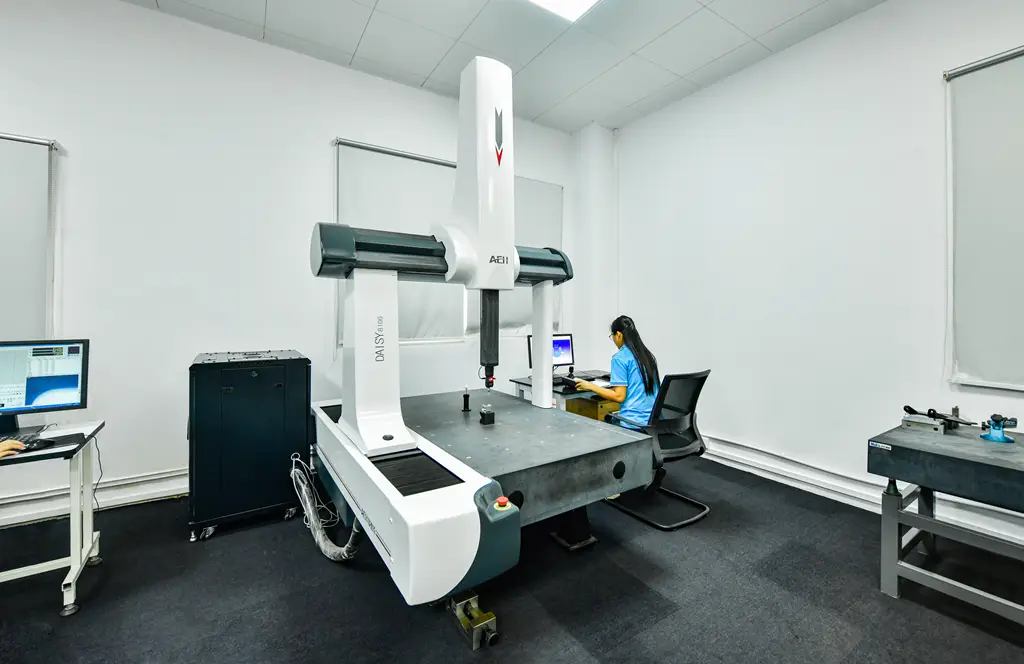
Material and Revision Verification
Confirm grade, temper, thickness, grain orientation, drawing revision and quantity before cutting.
First-Off Angle and Dimension Check
Measure bend angle, flange length, overall formed dimensions and critical interfaces before continuing the full batch.
In-Process Monitoring
Check features vulnerable to springback, distortion, tooling marks, reversed orientation or tolerance accumulation.
Final Inspection after Secondary Work
Confirm dimensions that can change during welding, hardware installation or coating, along with visual condition and packaging requirements.
Sheet Metal Bending Design Guidelines
Treat the following values as practical DFM starting points, not universal guarantees. Final limits depend on material grade and temper, thickness, bend direction, punch radius, V-opening, flange length, part size and cosmetic requirements.
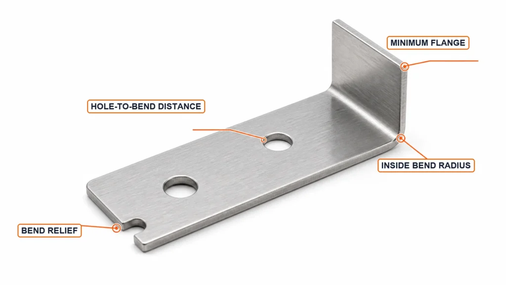
Use a Practical Inside Bend Radius
An inside radius near the material thickness is a common starting point for ductile sheet. Stainless steel, harder tempers and 6061-T6 aluminum may require larger radii to reduce cracking risk.
Provide Enough Flange for the Tooling
A flange must span the die opening and register against the backgauge. Very short flanges may require a smaller V-opening, special tooling or a design change. Ask for review instead of relying on one universal formula.
Keep Holes and Slots Clear of Bend Zones
Features close to a bend can stretch or become oval. A starting edge-to-bend clearance of approximately the inside radius plus two material thicknesses is often easier to form, but the final requirement is feature-specific.
Add Bend Relief at Intersecting Edges
Relief slots or notches can prevent tearing and material build-up where a bend terminates near an edge or another bend. Relief width and depth should match material thickness and the intended corner condition.
Control Grain Direction on Crack-Sensitive Materials
When possible, orient critical bends across the rolling direction rather than parallel to it. This is especially important for aluminum and higher-strength sheet.
Dimension the Formed Part from Functional Datums
Avoid chain dimensions across many bends. Identify the overall width, mounting faces, hole positions and assembly interfaces that matter after forming.
Supply STEP, PDF and Flat Data Consistently
The folded STEP model, drawing and DXF must use the same revision, units and geometry. Mark bend direction and cosmetic surfaces when they are not obvious.
Sheet Metal Bending FAQs
What files should I send for a bending quote?
Send a folded STEP model and a 2D PDF drawing that defines material, thickness, bend angles, inside radii, tolerances, finish and inspection notes. Add a DXF when the flat pattern has already been approved.
What tolerance can CNC bending achieve?
Tolerance depends on material, thickness, flange length, tooling, bend sequence, springback and measurement method. Critical linear and angular requirements should be reviewed feature by feature instead of using one universal value.
How do you control springback?
The bend program, tooling choice and first-off measurements are adjusted for the actual material. A test bend or representative sample may be used when material condition or angular requirements justify it.
Can holes be placed close to a bend?
They can distort when they fall inside the bend-affected zone. Provide the drawing for DFM review; moving the feature, adding relief or changing the sequence may be recommended.
Which aluminum is easier to bend?
5052 is commonly preferred for formed sheet-metal parts. 6061-T6 is less ductile and normally needs a larger radius and careful grain orientation.
Can you make closed boxes or deep channels?
Often yes, but later bends can collide with existing flanges. Segmented or gooseneck tooling, a revised sequence, split construction or welding may be required.
Will the tooling mark cosmetic surfaces?
Press brake tools can leave contact marks. Identify cosmetic faces and surface requirements so protective film, clean tooling, no-mark materials or an alternative route can be evaluated.
Can SAMSHION cut, bend, weld and finish one assembly?
Yes, when the complete route is included in the quotation. Send the assembly model and drawing so datums, weld sequence, coating and final inspection can be planned together.
How can I reduce sheet metal bending cost?
Use common material and thickness, practical bend radii, accessible bend sequences, standard tooling, consistent bend direction where possible and tolerances limited to functional features.