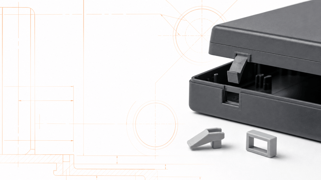
lastic snap fits join molded components without separate screws, adhesives or welding. When the geometry, material and mold strategy are developed together, a snap joint can shorten assembly time, reduce part count and make servicing easier. When those decisions are separated, the same feature may crack during assembly, relax under load, become difficult to mold or fail to hold the required gap.
This guide explains how to design injection-molded snap fits as an engineering system. It covers joint types, cantilever geometry, strain and force, material behavior, tolerances, mold release, failure diagnosis and validation. The numerical values below are starting points for design review, not universal pass/fail limits. Final dimensions must be checked against the selected resin grade, molded fiber orientation, temperature, moisture condition, assembly speed, expected service life and production tolerances.
Quick answer: A reliable plastic snap fit keeps peak strain below an application-specific allowable value, uses a gradual flexible beam with a generous root transition, provides a controlled lead-in and retention surface, accommodates the complete tolerance stack, and can be released from the mold without damaging the part. The design should then be verified with resin-specific data, simulation where appropriate, and molded-part testing.
What Is a Plastic Snap Fit?
A plastic snap fit is an integral joining feature that temporarily deflects during assembly and then returns toward its original position to engage a mating edge, groove or undercut. The flexible member supplies the spring action; the hook or bead provides retention; and the mating component supplies the reaction surface.
Snap fits are frequently produced by injection molding because the beam, hook, locators and surrounding housing can be formed in one cycle. This can eliminate purchased fasteners and secondary assembly operations. The economic advantage is real only when the feature also supports consistent molding, ejection, automated assembly and field performance.
A snap fit should not automatically be treated as a permanent joint. Depending on the return angle, access for release and expected strain cycle, it may be designed for one-time assembly, occasional service or repeated operation. That intended duty must be defined before the geometry is finalized.
Common Types of Injection-Molded Snap Fits
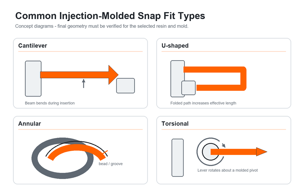
Cantilever Snap Fits
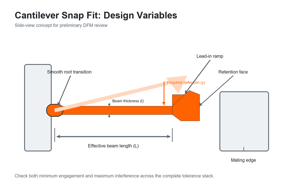
The cantilever snap fit is the most common form. A beam is fixed at one end and carries a hook near the free end. During assembly, the mating part rides over the lead-in ramp and bends the beam. Once the hook clears the mating edge, the beam recovers and the retention face engages.
Cantilever snaps are easy to understand and can be arranged around housings, covers, bezels and connectors. Their performance depends strongly on beam length, thickness profile, root condition, hook geometry and available deflection space.
U-Shaped and L-Shaped Snap Fits
When packaging space does not permit a long straight beam, the load path can be folded into a U or L shape. The added effective length can reduce strain for a required hook travel, but the turns must be radiused and the mold-release direction must be considered. A compact plan view does not necessarily mean a simple tool.
Annular Snap Fits
Annular snaps use a circumferential bead and groove, commonly on caps, plugs and cylindrical components. Assembly expands or compresses one of the rings. Performance depends on diameter, wall stiffness, bead height, friction and how much of the circumference is allowed to deform. Annular joints require a different calculation method from a straight cantilever.
Torsional Snap Fits
A torsional snap fit uses twisting rather than primarily bending a straight beam. It can be useful for levers or release tabs, but the local section, pivot geometry and stress distribution require careful analysis. Do not apply cantilever-beam formulas directly to a torsional feature.
How a Snap Fit Works: Deflection, Strain and Force
Three related values control a snap joint: required deflection, maximum strain and assembly or retention force.
Required deflection is the travel needed for the hook or bead to clear the mating feature. It includes nominal engagement plus any additional travel caused by dimensional variation, misalignment and assembly path.
Maximum strain normally occurs near the root of a cantilever beam. For a simple constant-thickness rectangular cantilever with small deflection, a first estimate of outer-fiber strain is:
strain = 1.5 x beam thickness x tip deflection / beam length squared
This relationship shows why increasing beam length is so effective: strain falls approximately with the square of length in the simplified model. However, real snap features may have tapered beams, large deflection, curved load paths, molded-in stress, anisotropic reinforcement and contact that moves during assembly. Use the equation as a screening calculation, not final proof.
Assembly force depends on beam stiffness, required deflection, lead-in angle, surface friction and the way the mating parts are guided. Retention force depends on the return angle, engagement, friction, local stiffness and whether the joint is intended to release. A higher hook does not automatically create a better joint; it may increase deflection and assembly force faster than it improves retention.
Covestro’s Snap-Fit Joints for Plastics design guide provides geometry-specific equations and distinguishes cantilever, annular and torsional concepts. BASF also provides a resin-focused Snap-Fit design tool for preliminary force and deflection estimates. These resources reinforce an important rule: use the calculation method that matches the actual joint and material instead of applying one universal percentage to every design.
Define the Joint Requirements Before Designing the Hook
The best snap-fit design process begins with the assembly and service requirement, not with a copied hook dimension.
1. Classify the Joint Duty
Decide whether the joint is:
- Permanent after one assembly.
- Serviceable a limited number of times.
- Repeatedly actuated during normal use.
A permanent snap may use a steep return face and hidden engagement. A serviceable joint needs controlled release access and enough fatigue margin for the expected cycles. A repeatedly operated latch should be designed more like a spring mechanism than a simple assembly aid.
2. Define Loads and Environment
Document the required retention load, impact or vibration exposure, operating temperature, chemicals, UV exposure, humidity and expected lifetime. Thermoplastics are time- and temperature-dependent. A joint that holds at room temperature immediately after molding may lose force after prolonged heat or sustained deflection.
3. Establish the Assembly Path
Identify insertion direction, allowable assembly force, alignment features, fixtures and whether assembly is manual or automated. Locators should control lateral position before the hook sees substantial load. Using the flexible snap beam as the primary alignment feature often creates twisting and unpredictable insertion force.
4. Build the Tolerance Stack
Include the molded dimensions of both components, mold shrinkage variation, tool wear, warpage, assembly fixture variation and any coating or texture that changes contact. Analyze both limits:
- At minimum engagement, the hook must still retain the mating part.
- At maximum interference, the beam must still assemble without excessive strain or force.
Use injection molding shrinkage data early because shrinkage and warpage can change hook position, enclosure gap and effective engagement after cooling.
5. Select the Resin Grade and Condition
Use the supplier’s grade-specific modulus, stress-strain curves, creep data, fatigue behavior and conditioning requirements. Generic family names such as ABS, nylon or PC are not enough for a final design. Grade, additives, recycled content, moisture and fiber orientation can materially change performance.
Cantilever Snap Fit Design Guidelines
The following rules are practical starting points for a straight cantilever. They must be scaled and verified for the selected resin and load case.
Use Length to Reduce Strain
Provide the longest effective beam that packaging allows. If a short beam must travel far, strain rises rapidly. A U-shaped beam, relief slot or tapered section can increase effective flexibility without making the housing larger. Avoid shortening the beam simply to make the CAD model look compact.
Control Beam Thickness and Taper
A uniform beam is simple to mold and calculate, but its bending stress is concentrated near the root. A gradual thickness or width taper can distribute strain more evenly and reduce material where it contributes little to spring action. The transition must be smooth; an abrupt step creates a new stress concentration.
Do not use a fixed beam-to-wall ratio as a universal rule. A preliminary ratio can help create the first model, but allowable deflection must still be calculated with the real length, thickness, material modulus and strain limit.
Add a Generous Root Transition
The beam root should blend into the supporting wall with a smooth fillet or tapered transition. A sharp inside corner concentrates strain, impedes material flow and can become the origin of a crack. The outside transition should also avoid a local thick mass that creates sink or long cooling time.
Separate Lead-In and Retention Functions
The lead-in ramp controls assembly. A shallower ramp generally reduces the axial force needed to deflect the beam, although friction and packaging limit how shallow it can be. The return face controls retention and release. A near-vertical return face supports permanent engagement; a deliberate release angle and tool access are required for serviceable engagement.
Treat angle recommendations as starting ranges, not isolated specifications. Contact radius, surface texture, lubrication, assembly speed and part stiffness can change the measured force substantially.
Limit Hook Projection to What the Joint Needs
Hook projection or undercut determines how far the beam must move. Add enough engagement to satisfy the retention and tolerance requirement, then avoid unnecessary extra height. Excess projection increases deflection, assembly force and mold complexity. A lead-in chamfer should be included in the tolerance model rather than drawn cosmetically after the design is complete.
Provide Deflection and Release Clearance
The beam needs physical space to move without hitting the housing, ribs or the mating part. Add clearance for the worst-case deflected shape and the assembly path. If the snap is serviceable, provide tool or finger access that releases the beam without prying against a cosmetic surface.
Guide the Parts Before Engagement
Add pilots, lips, rails or pins that establish position before the snap begins to deflect. The guides should carry shear and prevent racking after assembly so the hook primarily provides retention. This reduces side loading and makes insertion force more repeatable.
Choosing Materials for Plastic Snap Fits
Material selection should be based on the required strain, force retention, creep, fatigue, environment and molding behavior. The following comparison is directional; always confirm the exact grade with supplier data.
|
Material family |
Potential advantages |
Main cautions |
Typical snap-fit use |
|
POM / acetal |
Low friction, good spring recovery, dimensional stability and fatigue resistance in suitable grades |
Chemical compatibility, mold shrinkage and bonding limitations require review |
Repeated or precision latches, clips and moving mechanisms |
|
Unfilled PA / nylon |
Tough, fatigue resistant and capable of useful elastic deflection |
Moisture changes stiffness and dimensions; conditioning must match service |
Durable clips, automotive and industrial snap joints |
|
PP |
High elongation, low density and good integral-hinge behavior |
Creep and lower stiffness can reduce retention under sustained load |
Low-load closures, flexible consumer parts and one-piece assemblies |
|
PC and PC blends |
High impact strength and good dimensional capability in suitable grades |
Residual stress, chemical exposure and notch sensitivity must be controlled |
Housings and robust latches with moderate deflection |
|
ABS and ABS blends |
Good appearance, processability and economical housing production |
Lower fatigue and creep performance than spring-oriented resins in many grades |
Low-cycle enclosure snaps with controlled strain |
|
Fiber-reinforced grades |
High stiffness, strength and dimensional control along favorable fiber orientation |
Lower strain to failure, anisotropy and weld-line sensitivity can make thin flexible beams risky |
Low-deflection structural latches after simulation and molded testing |
|
PMMA or general-purpose PS |
Good appearance or low cost |
Notch sensitivity and relatively low toughness make aggressive snap deflection risky |
Only low-strain, carefully validated joints |
There is no universal rule that glass-filled nylon, polycarbonate or ABS must never be used. The correct conclusion is narrower: a stiff or notch-sensitive grade permits less geometric strain than a ductile, spring-oriented grade, so it needs a different beam geometry and validation plan.
For example, BASF’s engineering plastics calculation tools connect resin selection with snap-fit, creep and process calculations. This grade-specific approach is more useful than assigning one allowable strain to every POM grade.
Compare candidate resins using Samshion’s manufacturing materials guide, then obtain the exact supplier datasheet before freezing the snap geometry.
Injection Molding and Tooling Considerations
A mechanically successful snap can still be expensive or impossible to mold. Review the tool concept while the joint is being designed.
Undercut Release Strategy
The hook usually creates an undercut. Depending on its direction, size, resin and part flexibility, it may be released with:
- A straight-pull opening or pass-through window.
- A shutoff designed into the parting line.
- A lifter, slide or collapsible feature.
- Controlled stripping or flexing of the molded part.
Do not assume every plastic snap can simply be stripped from a rigid core. Forced ejection can whiten the beam, permanently deform the hook or damage the mold. A rapid tooling DFM review can determine whether a lower-complexity release method is realistic before production tooling is committed.
Draft and Texture
Add draft to faces that travel along the mold during ejection. The necessary draft depends on draw depth, resin, texture, polish and ejection method. Textured faces normally need more draft than polished faces. Keep the functional retention face separate from nonfunctional surfaces that need ejection draft.
Gate and Weld-Line Location
Avoid placing a weak weld line across the high-strain beam root when possible. Gate location controls flow direction and, in fiber-filled materials, fiber orientation. It also influences residual stress and warpage around the joint. Flow simulation is useful when a narrow beam, reinforced resin or difficult filling path makes these effects critical.
Uniform Sections Around the Root
Large local thickness at the root can cause sink, voids and uneven cooling. Core out the support and use ribs where stiffness is needed, while maintaining smooth load transfer into the beam. Link the joint review to the broader shrinkage and dimensional-control plan for the housing.
Ejection and Part Handling
Keep ejector pins away from delicate hooks unless their load is deliberately supported. Make sure robot grippers, conveyors and packing methods do not bend the snap before the part has cooled and stabilized. Early handling can create deformation that is not visible in a room-temperature CAD analysis.
Tolerance, Creep and Fatigue
Tolerance Stack
A snap joint is an assembly, not a single dimension. Include hook position, mating-edge position, wall thickness, shrinkage, warpage and assembly alignment. Run the stack in both directions and verify engagement, insertion force, enclosure gap and release clearance.
Creep and Stress Relaxation
Thermoplastics gradually deform or lose stress under sustained load, especially at elevated temperature. Avoid leaving the beam highly deflected after assembly. Ideally, the hook clears the mating edge and the beam recovers close to its neutral position, while the joint geometry, not permanent spring preload alone, maintains retention.
Fatigue and Repeated Service
For repeated use, the peak strain should be well below the one-time assembly limit and should be evaluated at the actual temperature, rate and environment. Test the complete joint through its expected cycle count, including a safety margin. Moisture-conditioned nylon and dry-as-molded nylon, for example, can behave differently.
Common Snap Fit Failures and Corrective Actions
|
Failure symptom |
Likely contributors |
Corrective direction |
|
Beam cracks during assembly |
Excessive required deflection, short or thick beam, sharp root, low-toughness grade, weld line or cold part |
Increase effective length, reduce unnecessary engagement, improve the root transition, review gate location and select a suitable grade |
|
White stress mark near root |
Local plastic strain, notch, forced ejection or assembly misalignment |
Reduce peak strain, enlarge the transition, improve guiding and inspect the ejection path |
|
Assembly force is too high |
Steep lead-in, high friction, stiff beam, excessive interference or poor alignment |
Reduce required travel, extend or taper the beam, refine the ramp and add locating features |
|
Joint loosens over time |
Sustained beam deflection, creep, insufficient engagement, wear, thermal cycling or tolerance drift |
Let the beam recover after engagement, increase geometric retention appropriately and validate aged parts |
|
Joint will not release for service |
Return face too steep, no release access or surrounding parts block beam travel |
Add a controlled release angle, service window or tool-access feature |
|
Hook deforms during molding or ejection |
Inadequate draft, unsupported ejection, forced stripping, hot part handling or thin section |
Rework the tool-release strategy, add support and confirm cooling before ejection |
|
Inconsistent gap or engagement |
Differential shrinkage, warpage, weak locating scheme or incomplete tolerance analysis |
Add independent locators, balance wall sections and validate cavity-to-cavity dimensions |
Prototype and Production Validation Plan
Do not approve a snap fit from nominal CAD geometry alone. Use a staged validation plan.
Prototype the Assembly Path
Additive prototypes are useful for checking access, sequence, interference and ergonomics. Their modulus, layer direction, surface friction and fatigue behavior may differ substantially from the production resin, so do not use a printed snap’s force or cycle life as final material proof.
Measure Molded Samples
For functional approval, use the intended production resin and a representative molding process. If that resin is unavailable during early trials, test a technically justified equivalent and confirm the final design with the production material.
Test Force and Retention
Record insertion force and pull-off or release force rather than relying only on subjective feel. Test at the required assembly rate and temperature. If the application is serviceable, include repeated assembly cycles.
Condition and Age the Parts
Condition hygroscopic materials to defined moisture levels. Add elevated-temperature dwell, thermal cycling, chemical exposure, vibration or UV aging when relevant. Recheck force, engagement and visible damage afterward.
Confirm the Production Window
Run parts from more than one point in the molding process window. A design that functions only at one ideal packing pressure or mold temperature is not production-robust. Samshion can review the CAD file, resin, quantity and performance requirements through the online quote and DFM process.
Snap Fit DFM Checklist
- The joint duty is defined as permanent, serviceable or repeatedly actuated.
- Retention load, insertion-force limit, environment and required life are documented.
- The complete tolerance stack is checked at minimum and maximum engagement.
- Peak strain is calculated with a method appropriate to the joint type.
- Resin data is grade-specific and includes temperature, moisture, creep and fatigue where relevant.
- Beam length, thickness and taper are chosen together rather than by one fixed ratio.
- The beam root has a smooth load path without a sharp corner or thick sink-prone mass.
- Hook projection is no greater than needed for retention and tolerance.
- Lead-in, return face and service-release access match the intended assembly.
- Locators guide the components before the snap beam is loaded.
- Clearance exists for full deflection and for any release tool.
- Draft, texture, gate, weld line, fiber orientation and ejection are reviewed with the mold design.
- Molded samples will be measured and tested under relevant conditioning and aging.
Design Snap Fits With the Material and Mold in Mind
A dependable snap fit is not created by copying a hook from another product. It comes from balancing strain, force, retention, tolerance, material behavior and tooling. Longer effective beams, smooth root transitions, controlled engagement and independent alignment usually make a joint more forgiving. Resin-specific calculations and molded testing then establish whether the design will survive its real assembly and service conditions.
If you are developing a molded enclosure, clip or latch, submit the CAD files, selected resin, target quantity, assembly method and load requirements. Samshion’s engineering team can review the joint together with mold release, gate location, shrinkage, tolerance and production risk before tooling begins. Upload your CAD files for DFM feedback.
Plastic Snap Fit FAQs
What Is the Best Plastic for a Snap Fit?
There is no single best resin. POM, unfilled nylon, PP, PC blends and other engineering plastics can all be appropriate when their grade-specific strain, creep, fatigue, temperature and chemical behavior match the application. Select the resin first at the property level, then size and validate the beam for that grade.
What Is a Good Snap Fit Beam Thickness?
Beam thickness cannot be selected from a universal wall-thickness ratio. It must be solved with effective length, required deflection, material behavior and available force. A preliminary ratio may help start the model, but the resulting strain and molding capability must be checked.
Should a Snap Fit Stay Deflected After Assembly?
Usually, sustained high deflection should be avoided because it promotes creep and stress relaxation. Whenever possible, design the hook to clear the mating edge and allow the beam to recover close to its neutral position while geometric engagement provides retention.
Can Glass-Filled Nylon Be Used for Snap Fits?
Yes, but not as a direct substitute for an unfilled grade. Reinforcement increases stiffness and introduces orientation-dependent behavior while typically reducing allowable deflection. A reinforced snap should use resin-specific data, flow and structural analysis where needed, careful weld-line control and molded-part testing.
Can ABS or Polycarbonate Be Used for Snap Fits?
Yes, suitable ABS, PC and blend grades are widely used in molded housings. The joint must keep strain within the chosen grade’s capability and account for notch sensitivity, chemical exposure, residual stress, creep and the required number of cycles. Avoid blanket material bans.
Do Snap Fits Require Slides or Lifters in the Mold?
Not always. A pass-through opening, parting-line shutoff or controlled stripping approach may release some undercuts. Other geometries require a slide, lifter or collapsible feature. The correct choice depends on undercut direction, resin flexibility, part geometry, cosmetic requirements and tool life.
Can a 3D-Printed Snap Fit Validate the Production Design?
A printed prototype can validate packaging, access and assembly sequence, but it does not reproduce the exact anisotropy, surface friction, fatigue, creep or weld-line behavior of an injection-molded resin. Use molded samples for final force and durability approval.