Introduction: The Precision Roadblock in Your MIM Project
At Samshion, we often encounter a familiar challenge in metal component manufacturing: the gap between the theoretical capabilities of Metal Injection Molding (MIM) and the practical limits of post-process CNC machining, especially for tight internal radius.
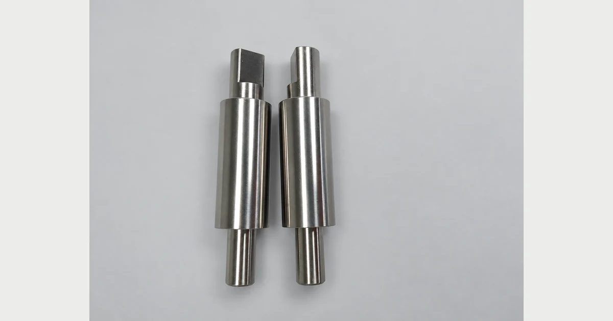
As shown in this project, even when MIM delivers a near-net-shape part, critical features like the R0.25mm internal corner on the sealing groove cannot be achieved directly. The MIM process alone cannot meet the tight tolerance, requiring CNC post-processing—but standard tooling also struggles to meet this radius requirement.
This blog breaks down this common manufacturing challenge and the solutions we implement at Samshion to deliver on custom’s 2D drawing specifications.
The Core Challenge: Why MIM + Standard CNC Fails at Internal Corners Smaller R0.25mm
The MIM Net-Shape Limitation
MIM is renowned for producing complex geometries with high volume efficiency. However, it is not a perfect “zero-tolerance” process. Fine features like sharp internal corners or small radius are particularly challenging:
Material Flow Issues
Metal powder and binder flow poorly into very narrow, sharp corners during molding, leading to incomplete fill or rounded edges.
Sintering Shrinkage
The sintering process introduces dimensional variation, making it impossible to guarantee tight tolerances on small features without secondary operations.
Surface Finish
The as-sintered surface roughness is too high for critical sealing or mating surfaces, requiring post-processing.
For these reasons, the part’s groove feature cannot be directly produced to spec via MIM alone, making CNC machining a necessity.
The CNC Machining Bottleneck
Once the part is molded and sintered, the next hurdle is machining the critical internal radius. Standard CNC processes face significant limitations here:
Tool Accessibility
Reaching into narrow, enclosed internal grooves requires extremely small cutting tools, which are prone to deflection, breakage, and poor surface finish.
Minimum Tool Radius
The smallest commercially available end mills often cannot reach the R0.25mm requirement, leaving a larger radius or tool marks in the corner.
Cycle Time & Cost
Attempting to machine such small features with micro-tools leads to long cycle times, high scrap rates, and increased costs.
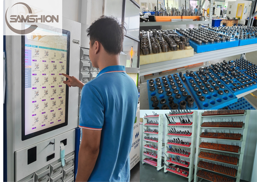
Samshion’s Solution: A Multi-Process Strategy for Precision
At Samshion, we don’t see these challenges as dead ends—we see them as opportunities to engineer a better process. Our approach combines material science, tooling innovation, and precision machining to meet custom’s specifications.
Step 1: Optimized MIM Pre-Machining Design
We start by adjusting the MIM mold to create a “near-net” feature that simplifies the CNC process:
Strategic Stock Allowance
We design the mold to leave a controlled, uniform layer of material on the groove walls, rather than trying to form the final radius. This ensures complete mold fill and reduces the material the CNC tool needs to remove.
Corner Geometry Adjustment
By slightly opening the corner in the mold, we eliminate potential sintering defects and create a stable starting point for the subsequent machining step.
Step 2: Precision Secondary Operations
With a robust MIM blank, we then apply specialized machining techniques to achieve the required R0.25mm corner:
Micro-Tooling & High-Speed Machining (HSM)
We use specialized, high-rigidity micro end mills on high-speed CNC machines. The combination of rigid tool holders, high spindle speeds, and low cutting forces allows us to machine tight radius with minimal deflection.
Electrical Discharge Machining (EDM) as a Backup
For the most challenging internal corners where cutting tools cannot reach, we deploy sinker or wire EDM. This non-contact process uses controlled sparks to erode the material, creating sharp, precise internal radius that would be impossible with conventional cutting.
Finishing & Deburring
Post-machining, we use precision polishing or mass finishing processes to meet the required surface roughness (Ra 1.6 in your drawing) and ensure no micro-burrs compromise the corner geometry.
Step 3: In-Process Quality Control
To guarantee every part meets the specs, we implement rigorous quality checks at every stage:
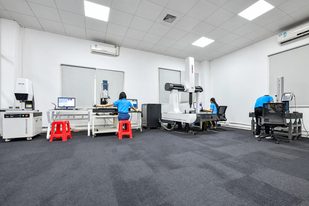
3D Metrology
We use coordinate measuring machines (CMMs) and optical comparators to verify the radius and dimensional accuracy of the machined features.
First Article Inspection (FAI)
We perform a full FAI on the first production run to confirm all tolerances, including the critical R0.25mm corner, are met before full-scale production begins.
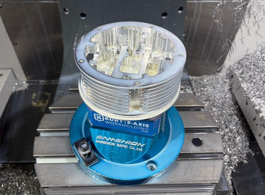
A key truth in precision manufacturing: there is no single “best” process, only the best combination of processes for specific requirements.
At Samshion, our expertise lies in navigating these complexities. We don’t just make parts—we engineer solutions. Whether it’s optimizing the MIM process, selecting the right secondary machining operations, or performing the final quality checks, we work closely with you to ensure your design intent is fully realized, even for the most challenging features.
If you’re facing similar manufacturing hurdles with your custom metal components, our team of engineers is ready to collaborate with you. Contact Samshion today to discuss your project and discover how we can turn your complex drawings into high-quality, functional parts.