Rapid CNC prototyping can compress weeks of conventional scheduling into a few working days, but speed does not come from running a machine recklessly. It comes from removing uncertainty before production begins. A supplier must receive controlled files, understand the functional requirements, select available material, plan stable workholding, program an efficient sequence and agree on an inspection and finishing route that fits the required date.
A 3-day CNC prototype should therefore be treated as a project-specific manufacturing target. It is most realistic for a small quantity of parts made from stocked material, with accessible geometry, clearly defined tolerances, standard tooling, limited secondary processing and prompt customer approval. Complex five-axis work, unusual alloys, deep features, special heat treatment, cosmetic finishing, comprehensive documentation or late design changes may require additional time.
This guide explains how engineers and purchasing teams can evaluate whether a rapid route is feasible. It also separates production lead time from shipping time, so the promised date is clear before work starts. For a project-specific assessment, submit the model and drawing through Samshion’s instant quote page and identify the required ship date, destination and critical dimensions.
What Does Rapid CNC Prototyping Mean?
Rapid CNC prototyping uses the same fundamental milling, turning, drilling and inspection principles as conventional CNC manufacturing. The difference is the way the project is organized. A quick-turn route reduces waiting between engineering review, programming, setup, machining and inspection. It does not remove the need for those steps.
The prototype may be used for form, fit and function checks, assembly trials, sealing tests, thermal evaluation, investor demonstrations, pilot builds or design verification. These purposes do not require the same evidence. A visual model can often accept wider tolerances and a simple finish, while a functional valve body may need controlled bores, flatness, surface texture and pressure testing.
The project objective should be stated before the supplier chooses a route. When the prototype must represent a future production part, the engineer should also identify which material condition, manufacturing features and finish must remain production-representative. Samshion’s broader rapid prototyping service can help compare CNC machining with additive manufacturing, vacuum casting and other processes when the best route is not yet known.
Production Time Is Not Delivery Time
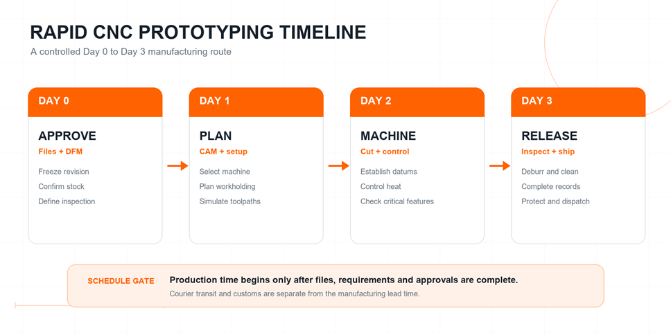
“Three days” can describe different milestones. It may mean three working days from order approval to machining completion, three days to shipment, or three days until the package reaches the customer. These are not equivalent.
The written quotation should state the trigger and endpoint. A clear definition might read: “Production lead time begins after the final CAD, drawing, material, finish, inspection scope and payment are approved. Parts are scheduled to ship on the third working day. Courier transit and customs clearance are additional.” This language prevents a machining target from being mistaken for a guaranteed arrival date.
Is Your Part Suitable for a 3-Day CNC Prototype?
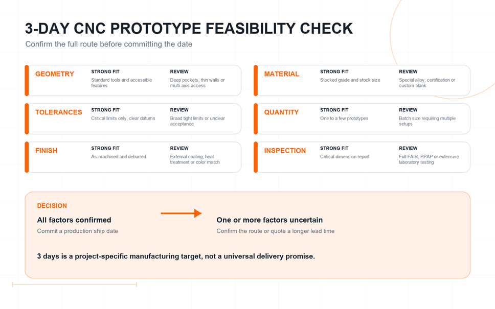
The fastest way to protect the schedule is to reject an unrealistic route before production. Use the following screening table during quotation.
|
Planning factor |
Strong fit for a 3-day route |
Possible with confirmation |
Usually needs more time |
|
Quantity |
One to a few prototype parts |
Small batch with repeated geometry |
Production quantity requiring process validation or multiple machines |
|
Material |
Stocked aluminum, common steel, stainless steel or engineering plastic |
Special size or condition available locally |
Imported alloy, certified lot, forging, casting or custom extrusion |
|
Geometry |
Accessible features and standard tools |
Multiple setups, thin walls, deep pockets or 5-axis access |
Extremely deep microfeatures, extensive EDM, special grinding or custom tooling |
|
Tolerances |
Functional tolerances applied only where needed |
Several tight relationships with a clear datum scheme |
Broad ultra-tight tolerances, incomplete datums or unclear acceptance method |
|
Finish |
Deburred or standard as-machined finish |
Simple blasting or locally available standard finish |
Multistage cosmetic finish, plating, heat treatment, passivation or matched color approval |
|
Inspection |
Critical-dimension report |
CMM program and defined sampling |
Full FAIR, PPAP, capability study, laboratory testing or customer source inspection |
|
Customer response |
Same-shift approval of questions |
One scheduled review window |
Slow approvals, changing files or unresolved specifications |
The decision is cumulative. A part can be simple in isolation but miss the target because the requested material is unavailable or the drawing requires a long external process. Conversely, a geometrically complex part may still be feasible when the model is stable, material is stocked, five-axis access eliminates refixturing and inspection is well defined.
Submit a Complete Quick-Turn CNC Package
The clock should not begin with an incomplete request. The supplier needs enough information to quote, program, manufacture and accept the part without guessing. A complete package normally includes the following items.
|
Required item |
Preferred content |
Delay prevented |
|
3D model |
STEP or another agreed neutral solid format, correct revision and units |
Geometry reconstruction and translation questions |
|
Controlled drawing |
Critical dimensions, datums, tolerances, threads, surface texture and notes |
Ambiguous acceptance criteria |
|
Material requirement |
Exact grade, temper or condition, color and certificate requirement |
Substitution and stock uncertainty |
|
Quantity |
Number of pieces per revision and any spares |
Incorrect setup and inspection planning |
|
Surface finish |
As-machined, blasting, anodizing or other defined process with masked areas |
Subjective terms such as “smooth” or “nice” |
|
Inspection scope |
Critical dimensions, report format, sampling, certificates and functional tests |
Rework after machining and reporting disputes |
|
Schedule |
Required ship date, destination, courier preference and arrival constraint |
Confusion between production and transit time |
|
Contact and approvals |
Engineer authorized to answer DFM questions promptly |
Idle time while the project waits for decisions |
The 3D model should represent nominal geometry. The drawing should not duplicate every model dimension, but it should communicate the features that control function and acceptance. ASME explains the role of its Y14.5 dimensioning and tolerancing standard in communicating geometric requirements. A coherent datum system helps the machine setup and inspection method reference the same functional relationships.
Day 0: Engineering Review and Schedule Confirmation
Day 0 is the approval stage before the committed manufacturing clock begins. Its purpose is to convert a request into a controlled route. The supplier checks files, verifies revision consistency, reviews manufacturability, confirms stock and secondary processes, identifies risks and returns focused questions.
Confirm Geometry and Tool Access
A milling cutter is round and must reach the surface through a physical path. Deep narrow pockets, sharp internal corners, long small-diameter holes and undercuts can require special tools or alternative processes. The CNC design for manufacturability guide explains how tool access, internal radii, wall thickness and setup count influence machining time.
An internal corner should have a radius compatible with an available end mill and an efficient cutting strategy. If a pocket corner is designed only marginally larger than the cutter, the tool may have to slow down and engage heavily. The dedicated internal corner radius guide provides more detailed design guidance.
Review Tolerances and Datums
The engineering review separates functional tolerances from default or inherited limits. A tight tolerance may be reasonable on a bearing seat and unnecessary on an outer clearance surface. Applying the same narrow limit everywhere increases programming, stabilization, finishing and inspection work.
The reviewer should ask which dimensions directly affect fit, sealing, alignment, motion or interchangeability. The drawing must also show the datum reference frame used to evaluate those dimensions. If the acceptance method is disputed, the project is not ready for a quick-turn commitment.
Freeze the Revision
The approved model and drawing receive a revision identifier. If the geometry changes after programming or material preparation, the supplier must assess whether the toolpath, fixture, stock size, inspection plan and quotation are still valid. A late revision can reset the schedule even if the visible change appears small.
Day 1: Process Planning, Programming and Workholding
After approval, manufacturing engineering selects the machine, stock, operations, tools, workholding and inspection checkpoints. This work is often the critical path for prototypes because setup effort is distributed across very few pieces.
Choose the Simplest Capable Machine
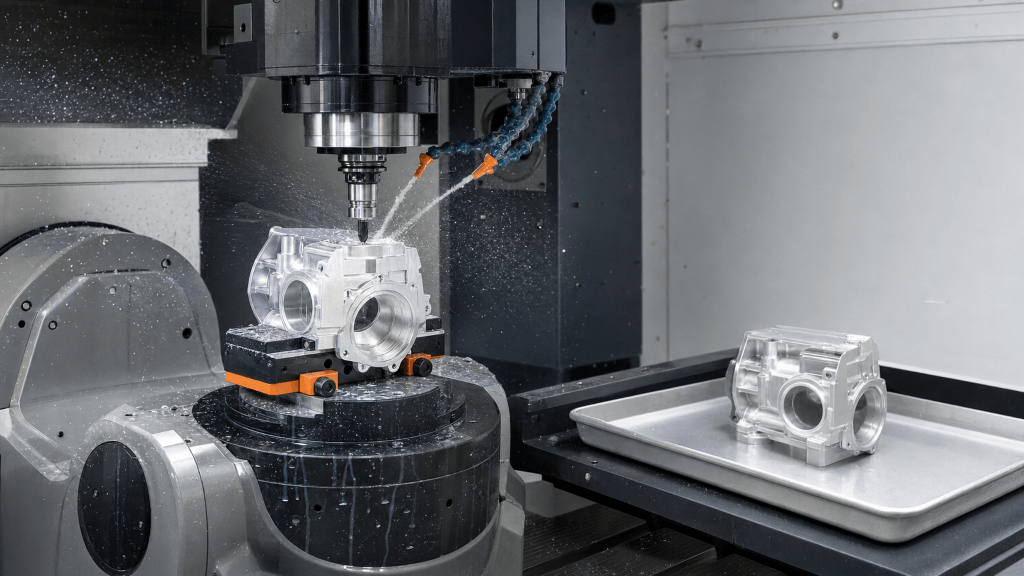
A three-axis machining center is usually efficient for prismatic parts with accessible faces. Indexed 3+2 or simultaneous five-axis machining can reduce setups for angled features and complex surfaces. The decision should be based on total route time and risk, not the prestige of the machine. Samshion’s 5-axis CNC machining page explains where multi-axis access can reduce refixturing.
Cylindrical parts may be better suited to CNC turning, possibly with live-tool operations. A process plan that matches the dominant geometry often saves more time than pushing every feature onto one machine type.
Plan Stable Workholding
The fixture must locate the part repeatably, resist cutting forces and provide tool access without distorting the workpiece. Standard vises, modular fixtures, collets and prepared soft jaws can shorten setup when they fit the geometry. Custom fixtures may be necessary for irregular, thin or delicate parts, but they add design, manufacture and validation time.
The CNC fixturing and setup guide explains why low-volume parts can have high setup cost and how datum selection, stock allowance and clamping surfaces affect the route. For urgent work, the engineer should preserve practical clamping areas where possible.
Program, Simulate and Prove the Route
The CAM programmer creates roughing, semi-finishing, finishing, drilling and inspection operations. Toolpaths are checked for tool and holder clearance, remaining stock, approach moves, workholding interference and machine travel. Simulation reduces risk, but it does not replace a controlled setup and prove-out.
Tool data should match the actual tool assembly. Sandvik Coromant’s milling knowledge resources describe how tool engagement, stability and application conditions affect milling performance. Quick-turn work still requires conservative judgment where the setup, material or feature is uncertain.
Day 2: CNC Machining and In-Process Control
Day 2 is the main stock-removal and feature-generation stage for a suitable part. Material identity, machine preparation, tool condition, work offsets and fixture location are verified before cutting.
Establish Datums Before Critical Features
The first operation creates or references surfaces that locate later operations. If the part must be flipped, the second setup should reference stable, well-defined features rather than unfinished or flexible surfaces. A poor datum transfer can create position or parallelism error even when each local size is correct.
Control Heat, Deflection and Residual Stress
Material removal changes the stiffness and stress balance of the blank. Thin walls can move when unclamped, plastics can respond to heat and moisture, and slender tools can deflect in deep features. The process may require balanced stock removal, staged roughing and finishing, rest periods or extra support.
The thin-wall CNC machining guide explains how wall geometry, cutting force, clamping and sequence interact. For urgent prototypes, it is often faster to change a nonfunctional thin feature than to force an unstable design through repeated corrective passes.
Use In-Process Checks Intentionally
On-machine probing, tool measurement and manual checks can verify work offsets, stock position, critical diameters and process drift. Renishaw describes applications for machine-tool probing and tool setting. These systems help control the process, but they do not make the machine automatically correct every dimensional or surface problem.
The inspection plan should identify what is checked during machining and what is verified after the part reaches a stable condition. Measuring every dimension repeatedly can slow the route without reducing meaningful risk.
Day 3: Deburring, Inspection, Release and Shipping
On Day 3 the supplier completes the agreed edge treatment, cleaning, inspection, documentation, packaging and release. If an external finish is required, this sequence may extend beyond the three-day route.
Apply Only the Required Finish
The fastest standard result is often an as-machined and deburred part. Blasting, polishing, anodizing, plating, passivation, heat treatment and painting add process steps and may change dimensions or edge condition. Before committing a date, confirm whether the quoted lead time includes those operations.
Samshion’s CNC machining surface finish guide explains how machining marks, roughness, cosmetic expectations and downstream finishes should be specified. Use objective requirements instead of visual adjectives.
Inspect Against an Agreed Plan
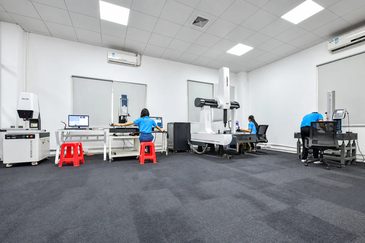
Final inspection should follow the drawing, model and approved scope. Calipers and micrometers may be suitable for accessible sizes. Height gauges, bore gauges, optical equipment, surface roughness instruments or a coordinate measuring machine may be needed for other characteristics.
The CNC machining inspection guide provides a framework for selecting methods and records. Samshion’s quality assurance page describes the broader inspection and traceability system. A rapid project should define whether the customer needs a critical-dimension report, full dimensional report, material certificate or first-article package before production starts.
Package and Communicate the Release
Parts should be clean, dry and protected from contact damage. Delicate finishes, sharp edges, threads and sealing surfaces may need individual wrapping or protective caps. The shipment notice should identify the order, revision, quantity, inspection documents, courier tracking number and ship date.
What Usually Extends CNC Machining Lead Time?
|
Delay source |
Why it changes the route |
Practical prevention |
|
Conflicting model and drawing |
The supplier cannot know which requirement controls |
Submit one revision and list any controlled exceptions |
|
Unavailable stock |
Purchasing and incoming verification become critical-path tasks |
Accept a qualified stocked alternative only when function permits |
|
Unnecessary tight tolerances |
Additional finishing, stabilization and inspection may be required |
Apply tight limits only to functional relationships |
|
Deep or inaccessible features |
Long tools, EDM, special drills or extra setups may be needed |
Increase radii, open access or separate the assembly if acceptable |
|
Thin and flexible geometry |
Clamping and cutting can distort the part |
Add temporary support, increase thickness or use staged machining |
|
Custom threads or tooling |
Tool sourcing and prove-out add time |
Use standard thread forms, diameters and cutters where possible |
|
External finishing |
Parts leave the machining cell and enter another queue |
Use as-machined or locally available standard finishes for urgent trials |
|
Extensive documentation |
Programming and inspection capacity must be scheduled |
Limit reports to the evidence needed for the prototype decision |
|
Late design changes |
Programming, stock and inspection work may become obsolete |
Freeze the revision before authorizing production |
|
Slow answers |
Machines and programmers cannot proceed through ambiguity |
Assign an engineer who can approve DFM questions promptly |
How to Reduce Lead Time Without Reducing Function
The objective is not to make the drawing less rigorous. It is to concentrate rigor where it controls function.
Prioritize Critical-to-Function Features
Identify the interfaces that determine assembly, sealing, bearing alignment, motion or test performance. Give those features explicit datums, tolerances and inspection methods. Leave noncritical clearance and cosmetic regions at standard machining capability when possible.
Separate Prototype and Production Requirements
A prototype may not need the complete production finish or documentation package to answer the current engineering question. For example, a fit-check part can be machined and deburred first, while color matching is evaluated on separate finish coupons. Record any difference so the prototype is not mistaken for the final production specification.
Choose Stocked Materials and Standard Features
Common stock sizes, standard thread forms, standard reamer sizes and available cutters reduce procurement and setup risk. Samshion’s manufacturing materials guide can help identify common alternatives, but any substitution must be approved against mechanical, thermal, chemical, regulatory and appearance requirements.
Approve a Defined Inspection Scope
Do not request a full report by default if only a few features determine the test. Conversely, do not remove evidence needed to trust the prototype. A concise critical-characteristic plan is usually faster and more useful than an indiscriminate report covering every model dimension.
Example Three-Day Project Scenarios
|
Scenario |
Likely route |
Schedule judgment |
|
Two aluminum 6061 sensor housings, as-machined, standard threads and five critical dimensions |
Stock confirmation, 3-axis or 3+2 milling, deburr and critical-dimension report |
Strong candidate after DFM approval |
|
One stainless steel manifold with deep intersecting holes and a leak test |
Milling, deep-hole strategy, deburr, cleaning and functional test |
Possible only after tool access and test capacity are confirmed |
|
Four thin POM covers with broad flatness requirement |
Balanced machining, controlled clamping and conditioned inspection |
Requires material and stability review; three days may be risky |
|
One complex titanium impeller with simultaneous 5-axis surfaces and full CMM report |
Multi-axis programming, specialized tooling and extensive inspection |
Usually needs a longer qualified route |
|
Ten anodized cosmetic panels with matched color and no visible fixture marks |
Machining plus external cosmetic process and approval |
Finish queue normally controls the date |
These examples are screening tools, not guarantees. The actual route depends on dimensions, stock, machine capacity, finish, inspection and the supplier’s current schedule.
Rapid CNC Prototyping Quality Checklist
Before release, confirm the following:
- The final model and drawing have the same revision and units.
- The material grade, condition and certificate requirement are approved.
- Critical dimensions, datums, threads, edge requirements and surface texture are defined.
- The quoted date states when the clock starts and whether it ends at completion, shipment or delivery.
- Any external finish, heat treatment or testing is included in the schedule.
- The workholding and setup plan protect critical relationships.
- The inspection scope and report format are agreed before machining.
- Customer questions have a named approver and response deadline.
- Packaging protects functional and cosmetic surfaces.
- The shipment includes revision, quantity, records and tracking information.
Rapid CNC Prototyping FAQs
Can every CNC part be produced in three days?
No. A three-day route depends on geometry, quantity, material availability, tooling, setups, tolerances, finish, inspection, documentation and current capacity. The supplier must review the complete package before committing.
When does the three-day clock begin?
It should begin only after the final files, quotation, material, finish, inspection scope and commercial approval are complete. The quotation should state this trigger explicitly.
Does three-day production include international shipping?
Not automatically. Production time, ship date and courier transit are separate milestones. Customs, weather and carrier operations are outside the machining process and should be planned separately.
Which materials are fastest for rapid CNC prototypes?
Stocked, machinable grades in available sizes usually support the shortest route. Aluminum 6061 and common engineering plastics are frequent candidates, but the correct choice depends on function. Do not substitute material solely for speed without engineering approval.
Do tight tolerances always make the part better?
No. A tolerance is valuable when it protects function and can be verified with an agreed method. Unnecessary tight limits can increase cycle time, stabilization, scrap risk and inspection effort without improving the test result.
Can anodizing or plating fit a three-day schedule?
Sometimes, but only when the process, color, masking, dimensional effects, supplier capacity and transport are confirmed. Standard as-machined and deburred parts are usually easier to expedite.
What files should I send for a quick quote?
Send a neutral 3D solid model, controlled drawing, material and quantity, finish, inspection needs, required ship or arrival date, destination and contact for DFM approvals.
Should I choose 5-axis machining for every urgent part?
No. Five-axis machining can reduce setups for complex multi-face geometry, but a three-axis or turning route may be faster and less expensive for simpler parts. Choose the simplest capable process based on total route time.
Conclusion
Rapid CNC prototyping is a controlled workflow, not a promise that every design can bypass engineering. A credible three-day route begins with complete files and a frozen revision. It then connects DFM, stock confirmation, process selection, stable workholding, verified programming, controlled machining, focused inspection and clear release criteria.
The best way to shorten lead time is to remove ambiguity and concentrate requirements on the features that determine function. When geometry, material, quantity, finish and inspection fit the route, quick-turn CNC machining can deliver useful physical evidence in days. When they do not, an honest schedule and an alternative process are more valuable than an unrealistic commitment.
To obtain a project-specific timeline, upload your CAD files with the controlled drawing, material, quantity, finish, inspection scope and required destination date.