6061 aluminum is a practical starting point for CNC-machined housings, brackets, plates, fixtures and functional prototypes. It combines useful strength, relatively low density, corrosion resistance, broad stock availability and good machinability. Those advantages make it suitable for many products, but they do not create a universal tolerance capability.
A statement such as “6061 can hold +/-0.005 mm” is incomplete unless it identifies the controlled feature, nominal size, geometry, datum system, stock form and temper, process sequence, surface treatment, measurement method and inspection temperature. A short accessible bore in a rigid block behaves differently from a long thin wall, a large flat plate or a hole pattern located from weak datums.
This guide explains how to plan 6061 aluminum CNC machining without turning one attractive tolerance number into an unrealistic whole-part promise. It covers alloy temper, dimensional stability, workholding, machining strategy, design for manufacturability, surface finishing, inspection and quotation requirements.
Quick Answer: Can 6061 Aluminum Be Machined to +/-0.005 mm?
It may be possible to achieve a total tolerance band of 0.010 mm on selected, stable and accessible features of a suitably designed 6061 part. It should not be treated as the standard tolerance for every dimension or as a guarantee across an entire component.
Feasibility depends on at least the following conditions:
- the exact feature type, size and relationship to the datum reference frame;
- sufficient material around the feature to resist cutting and clamping loads;
- suitable stock condition and a documented alloy and temper;
- balanced material removal and a controlled roughing-to-finishing sequence;
- rigid, repeatable workholding that does not distort the released part;
- stable tools, process temperature and chip evacuation;
- a measurement method with enough resolution and acceptable uncertainty;
- inspection after the part has stabilized at the agreed reference temperature; and
- confirmation that anodizing, coating or other post-processing will not invalidate the result.
The correct question is therefore not “Can your machine hold five microns?” It is “Can this defined feature on this part be produced and verified within this tolerance under an agreed process and inspection plan?” A capable spindle does not remove material stress, thermal expansion, datum ambiguity or measurement uncertainty.
For a realistic quotation, identify critical-to-function features and allow appropriate general tolerances elsewhere. This approach improves both manufacturing reliability and cost.
What Is 6061 Aluminum?
6061 is a heat-treatable aluminum alloy in the 6000 series. Magnesium and silicon are its principal alloying additions. Hydro describes 6061 as a heat-treatable magnesium-silicon alloy and publishes an official 6061 alloy data sheet for its North American extrusion products.
The alloy is commonly selected for machined components because it offers a useful balance of properties rather than the maximum value in one category. Typical applications include structural brackets, instrument housings, manifolds, fixtures, robotic components, electronic enclosures and prototype assemblies.
Material properties depend on product form, temper, thickness, governing specification and supplier data. Do not copy a single strength value from a generic material page into a safety-critical design. Specify the required material standard and obtain the applicable mill certificate when traceability matters.
Why 6061 Is Commonly Chosen for CNC Parts
6061 generally machines with lower cutting forces than many steels, and suitable cutting tools can produce clean pockets, bores and edges. Its broad availability in plate, bar, tube and extrusion can shorten sourcing time. It also supports several finishing routes, including bead blasting, chemical conversion coating, anodizing, paint and powder coating.
However, “easy to machine” does not mean “immune to distortion.” A rigid 6061 block with moderate material removal may remain stable, while a thin frame cut from thick plate can move after clamps are released. The amount and symmetry of removed material often matter more than the alloy family alone.
6061-T6 vs 6061-T651 for CNC Machining
The temper designation describes processing applied after alloy production. It is not a cosmetic suffix.
6061-T6
T6 indicates solution heat treatment followed by artificial aging. It provides a useful combination of strength and hardness. T6 stock can be appropriate for many machined parts, especially when the geometry is compact and material removal is not severely unbalanced.
6061-T651
T651 includes stress relief by controlled stretching in addition to the T6 heat-treatment route. This processing reduces residual stress, which can improve dimensional predictability when machining plate. It does not make distortion impossible, and it does not guarantee that every part will remain flat after aggressive or asymmetric material removal.
The exact temper available also depends on product form. Extruded products may use designations such as T6511. Purchase the temper that matches the drawing and confirm substitutions rather than treating all T6-family suffixes as interchangeable.
Which Temper Should You Specify?
For a thick plate part with deep pockets, a large amount of stock removal or tight flatness requirements, stress-relieved plate can be a better starting point. For moderate geometry, common T6 stock may be sufficient. The choice should consider stock form, availability, mechanical requirements, distortion risk and cost.
Write the exact alloy, temper and product form on the drawing or purchase specification. If a supplier is allowed to propose an equivalent stock condition, require written approval before production.
There Is No Universal 6061 CNC Tolerance Table
General tolerance tables are useful for early estimation, but they cannot describe the capability of every feature. A tolerance must be connected to a defined dimension or geometric characteristic.
Feature Size and Type
A diameter, slot width, wall thickness, flatness requirement and positional tolerance create different machining and inspection problems. A small bore may be finished by reaming or precision boring. A wide pocket floor may be affected by tool reach and part flatness. A thin wall can spring after cutting, even when it measured correctly in the fixture.
Geometry and Accessibility
Short, rigid and directly accessible features are usually easier to control than deep cavities, long overhangs or features requiring multiple setups. Tool deflection increases with reach. Re-clamping introduces another opportunity for datum and orientation error.
Datum Strategy
The 3D model describes nominal geometry, but the 2D drawing should communicate the functional reference system and tolerances. ASME Y14.5 provides the established language for dimensioning and geometric tolerancing. A clear datum reference frame helps manufacturing and inspection reproduce the same functional interpretation.
Do not add a tight plus/minus tolerance to every coordinate if position, profile, perpendicularity or flatness better expresses the requirement. Over-dimensioning can create contradictory requirements and unnecessary inspection.
Tolerance by Risk, Not by Marketing Number
Use three practical classes during design review:
- Critical features control fit, sealing, alignment, motion or calibration. They require an explicit tolerance and inspection method.
- Functional but non-critical features require a defined general or feature tolerance appropriate to assembly.
- Clearance and cosmetic features should use economical tolerances unless a real function requires tighter control.
This classification prevents the tightest number on the drawing from becoming the default for the entire part.
What Causes Dimensional Error in 6061 Machining?
Dimensional variation usually comes from several small effects rather than one defective machine.
Residual Stress and Material Removal
Heat treatment, quenching, rolling, extrusion and stock preparation can leave residual stress. Machining redistributes that stress by removing material. A plate can move between roughing and finishing or after release from the fixture. Stress-relieved stock reduces risk but does not remove the need for balanced process planning.
Workholding Force
Clamps can bend thin or broad parts into the fixture. The machine then cuts the distorted shape. When the part is released, it springs toward its free state and may fail flatness, position or profile.
Cutting Force, Tool Deflection and Tool Wear
Long tools bend more than short tools. Thin walls can deflect away from the cutter. Built-up edge, poor chip evacuation or worn tools change cutting behavior and surface condition. The finishing strategy should use suitable tool reach, controlled engagement and predictable tool life.
Temperature
Aluminum responds noticeably to temperature change. Heat from cutting, coolant, handling and the room can affect both the workpiece and the measurement system. ISO 1:2022 defines the standard reference temperature used for geometrical and dimensional properties, and NIST explains why 20 degrees C is used for dimensional measurement.
A warm part measured immediately after machining can produce a result that changes as the part equilibrates. For tight work, define the inspection environment and allow sufficient stabilization before final acceptance.
Datum Transfer Between Setups
Turning a part over or moving it between machines creates a new location chain. Soft jaws, probing, qualified fixtures and stable datum surfaces can reduce error, but the drawing should avoid forcing unnecessary setup changes.
Burrs, Surface Texture and Coating
A burr can alter contact during measurement or assembly. A rough or interrupted surface may make a two-point measurement unreliable. Anodizing and coatings can affect size, and chemical pre-treatment can also remove or convert surface material. Finish allowances and masking must be planned before machining is finalized.
A Controlled Process for Tight-Tolerance 6061 Parts
Tight-tolerance machining should be managed as a process, not as one final finishing pass.
- Review the drawing and define functional datums. Resolve ambiguous dimensions, coating callouts and inspection requirements before programming.
- Confirm stock form, alloy, temper and certification needs. Select material thickness that allows cleanup without excessive removal.
- Plan balanced roughing. Leave controlled finishing allowance on critical surfaces and avoid removing most material from one side in a single clamping.
- Allow the workpiece to stabilize when geometry and tolerance justify it. A separate roughing and finishing stage can reveal movement before final dimensions are cut.
- Re-establish datums. Inspect or probe reference surfaces before semi-finishing and finishing.
- Finish critical features with short, stable tools and process-specific parameters. Control chip evacuation and tool life.
- Deburr and clean without rounding or damaging controlled edges and datums.
- Allow the part and measurement equipment to reach the agreed inspection condition.
- Inspect critical size and geometry using methods matched to the drawing.
- Apply the specified surface treatment, then inspect affected dimensions again when the finish can change them.
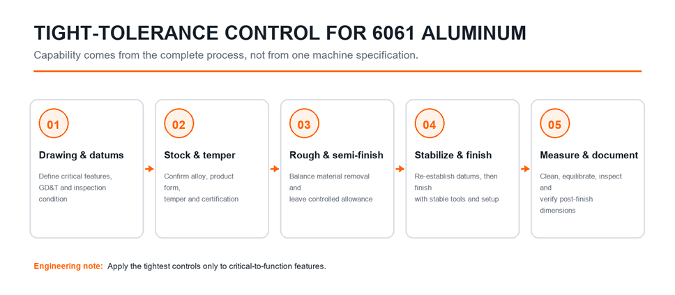
This sequence can be simplified for ordinary prototype work and expanded for critical production features. The required controls should match risk rather than being copied to every job.
Workholding and Thin-Wall Distortion
Thin walls, large window frames and pocketed plates require special attention because the released part may not retain the clamped shape.
Support the Part Without Over-Constraining It
Use broad, repeatable support near cutting loads. Clamp on robust regions and avoid point loads on thin walls. Fixture surfaces should be clean and free of chips. Vacuum fixtures, soft jaws, adhesive workholding, tabs or sacrificial supports may be useful for particular geometries, but each method has limits.
Balance Material Removal
Where practical, remove material in stages from opposing faces or symmetric regions. Avoid leaving one thin wall beside a massive section if the function permits a more balanced design. A roughing operation followed by rest and re-fixturing can reduce the amount of movement that occurs after final finishing.
Measure in the Free State When Function Requires It
Inspection results should represent the agreed part condition. A part that passes only while forced flat against a fixture may not function after assembly. If the assembly intentionally constrains the component, the drawing and inspection plan should state the required condition.

DFM Guidelines for 6061 Aluminum Parts
Good DFM does not remove the function of the part. It expresses that function with geometry that can be machined and inspected reliably.
Wall Thickness and Section Changes
Use consistent, sufficiently stiff walls where possible. Sudden transitions between heavy and thin sections can increase distortion risk. If a thin wall is essential, identify which face and relationship are functionally critical so the process can prioritize them.
Internal Corner Radii
Rotating end mills create radii in internal corners. A larger corner radius permits a larger, more rigid tool and can reduce machining time. Very small radii in deep pockets require smaller or longer tools, which increase deflection and cycle time. Our guide to the internal radius in milling explains why corner geometry affects tool selection.
Do not specify a sharp internal corner unless the design truly needs a secondary process such as EDM, broaching or another specialized method.
Deep Pockets and Narrow Slots
Deep cavities restrict chip evacuation and may require long-reach tools. Increase corner radii, open access or reduce depth where the product allows. If depth is unavoidable, avoid combining it with an unnecessarily tight tolerance and cosmetic roughness requirement on every surface.
Holes and Threads
Use standard drill sizes and thread forms where possible. Provide enough tool access and edge distance. For threaded blind holes, allow space beyond usable thread depth for the drill point and incomplete thread. Identify insert requirements, locking features and post-finish thread condition.
Tight hole tolerances should be applied to functional fits, not all clearance holes. If true position controls assembly better than coordinate tolerances, use a clear datum structure and positional requirement.
Mating Faces, Seals and Bearing Fits
Separate size, form and texture requirements. A bearing bore may require size and cylindricity; a sealing face may require flatness and surface texture; a bolted flange may depend mainly on hole position and contact area. One general plus/minus number cannot communicate all of these functions.
Make Critical Features Inspectable
If a feature cannot be reached by a probe, bore gauge or optical system, verification may require special fixturing or destructive methods. Discuss the measurement approach while the design can still be changed.
Choose the Machine Configuration from the Geometry
Machine selection should follow part geometry and setup strategy, not a claim that more axes are always more precise.
3-Axis CNC Milling
Three-axis milling is efficient for plates, brackets, open pockets and features that can be reached from a small number of orthogonal setups. A well-planned 3-axis process can provide excellent results on suitable geometry. Learn more about our CNC milling services.
5-Axis CNC Machining
Five-axis machining can reduce re-clamping and improve access to angled or multi-face features. Fewer setups may improve the relationship between features, but the outcome still depends on calibration, workholding, tooling, programming and inspection. Use 5-axis CNC machining when it materially reduces setups or reaches geometry that would otherwise require complex fixtures.
CNC Turning and Mill-Turn
Rotational components such as shafts, bushings and flanges are usually better suited to turning. Live tooling or mill-turn equipment can produce cross-holes, flats and secondary milled features while maintaining a rotational datum. The most effective process may combine turning and milling rather than forcing the entire part onto one machine type.
Toolpath, Chip and Heat Control
6061 often supports productive cutting, but tight features need predictable cutting conditions.
Use sharp tools with geometry suited to aluminum. Maintain chip evacuation so chips are not recut against the surface. Limit tool overhang and choose a tool diameter that balances access, rigidity and corner requirements. For walls and floors that can deflect, use step-downs and finishing paths that avoid sudden changes in cutting load.
The finishing allowance should be deliberate. Too little stock may leave roughing error; too much stock can create heat and deflection during the final pass. The correct value depends on feature size, tool, machine, workholding and prior operation.
Tool wear should be managed through inspection or planned life limits for production. A process that works on the first part but drifts through a batch is not capable merely because the machine repeats its programmed position.
6061 Aluminum Surface Finishes and Dimensional Effects
Finish selection must happen before the final tolerance plan is approved.
As-Machined
As-machined surfaces retain the texture produced by cutting and normal deburring. This route has the shortest process chain and avoids coating buildup. If texture is functional, specify the required parameter on the relevant surface rather than assuming one universal result.
Bead Blasting
Bead blasting can create a more uniform matte appearance and reduce the visibility of light tool-path variation. It can also affect edges and precision surfaces. Identify cosmetic zones and protect critical bores, threads, datums and sealing faces as required.
Anodizing
Anodizing converts the aluminum surface to aluminum oxide. Color, appearance and dimensional effect depend on alloy, surface preparation and process conditions. The Aluminum Anodizers Council notes that dimensional change depends on the anodizing process and alloy, and that etching or brightening steps can also affect dimensions.
Do not finish-machine a bearing fit to final size and then add an unspecified anodize process. Define coating type, class, thickness or performance requirement, color, sealing, masking and the dimensions controlled after finishing.
Chemical Conversion Coating, Paint and Powder Coat
Conversion coating may support corrosion protection, conductivity requirements or paint adhesion, depending on the specified class and system. Paint and powder coating add a more significant organic layer and normally require masking of close fits, grounding points, threads or contact surfaces. Use our surface finishing services guide to compare the main options.
For a detailed finish-selection framework, see CNC machining surface finishes.
Inspection and Measurement Planning
Inspection should be designed around the requirement, not selected after machining.
Match the Method to the Feature
Calipers are useful for many general dimensions but are not the universal tool for tight tolerances. Micrometers, bore gauges, height gauges, air gauges, surface instruments, vision systems and coordinate measuring machines each suit different tasks. Resolution alone does not equal measurement accuracy.
The inspection plan should identify the characteristic, datum setup, instrument or method, sampling level, acceptance rule and report format. For critical relationships, confirm whether the customer expects a CMM report, first article inspection, material certificate or full dimensional report.
Consider Measurement Uncertainty
The measurement system needs sufficient capability relative to the tolerance. Fixture repeatability, probe access, calibration, operator technique, surface condition and temperature all contribute uncertainty. A reported value with many decimal places is not automatically reliable.
Control Temperature and Stabilization
ISO 1 uses 20 degrees C as the standard reference temperature for geometrical and dimensional properties. For tight aluminum dimensions, record or control the inspection condition and avoid measuring a freshly machined warm part as if it were stable.
Inspect After Finishing When Required
If anodizing, coating, blasting or polishing can affect a controlled feature, the final acceptance inspection should occur after that process or the drawing should define separate pre-finish and post-finish requirements.
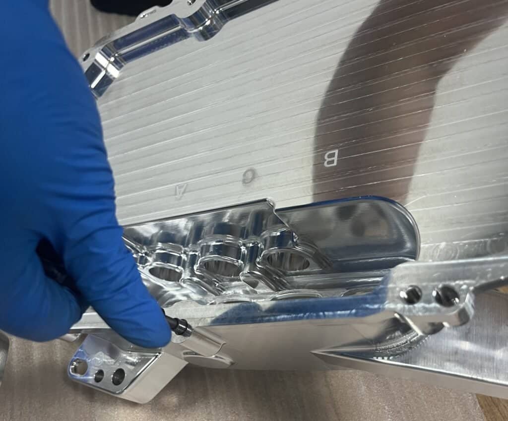
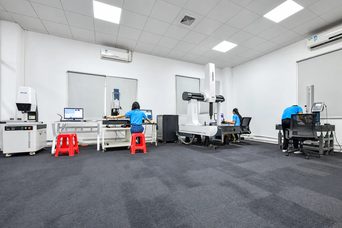
Samshion’s quality assurance process can be aligned with drawing requirements, material documentation and agreed inspection records.
What Increases the Cost of Tight-Tolerance 6061 Parts?
The largest cost increases usually come from added control, time and verification rather than from the raw alloy alone.
Tolerance Applied to Too Many Features
Every tight feature can add finishing passes, tool control and inspection. Apply the tightest tolerance only where the assembly or performance requires it.
Multiple Setups and Complex Datum Transfer
Features on many sides may require additional fixtures, probing and inspection. Redesigning access or using five-axis machining can sometimes reduce setups, but it should be evaluated against programming and equipment cost.
Thin Walls and Heavy Material Removal
These geometries may require staged roughing, stabilization, soft jaws, sacrificial support or slower finishing. A block that ends as a light frame also creates high material waste.
Small Internal Radii and Deep Features
Small tools and long reach reduce material-removal rate and increase deflection risk. Larger radii and accessible pockets often reduce both cycle time and risk.
Cosmetic Finish Combined with Tight Dimensions
Appearance standards, masking, coating allowance and post-finish inspection add operations. A physical limit sample may be needed for color or texture consistency.
Documentation and Sampling
Material traceability, first article inspection, full CMM reporting and 100 percent inspection provide value when required, but they are not free. State the documentation level in the RFQ so quotations are comparable.
6061 vs 7075 vs 5052: Select by Function and Process
No one alloy is best for every part.
|
Material |
Typical reason to consider it |
CNC and design considerations |
|
6061 |
Balanced strength, machinability, availability and finishing options |
Strong default candidate for machined housings, brackets, fixtures and prototypes; temper and geometry still affect stability |
|
7075 |
Higher strength where the design and environment justify it |
Higher material cost; corrosion, finishing, stock condition and engineering requirements need review; do not select only because it is called aerospace grade |
|
5052 |
Good formability and corrosion resistance for sheet-metal parts |
Often better suited to bending and fabricated sheet assemblies than heavily machined block geometry; not a direct replacement when heat-treatable strength is required |
Use the manufacturing materials guide to compare material families. Final selection should consider load, stiffness, fatigue, environment, joining, finish, stock form, certification and cost.
RFQ Checklist for 6061 Aluminum CNC Parts
Send the following information for an accurate manufacturing review:
- native 3D CAD or a neutral STEP file;
- a controlled 2D drawing with revision level;
- exact alloy, temper and stock-form requirements;
- quantity, prototype and future production expectations;
- clear datums and GD&T for functional relationships;
- identification of critical-to-function dimensions;
- thread, insert, edge-break and burr requirements;
- surface texture requirements only where functional;
- finish specification, color, masking and post-finish dimensions;
- inspection level, sampling, report and certification requirements;
- mating-part or assembly context when it helps explain the tolerance; and
- delivery location and required schedule.
Avoid using model precision or the number of decimal places as the tolerance definition. If a tolerance seems tighter than the function requires, allow the manufacturer to propose a documented alternative.
Frequently Asked Questions
Is 6061 aluminum easy to CNC machine?
6061 is generally considered a practical aluminum alloy for milling, turning, drilling and boring. Good results still depend on tool geometry, chip evacuation, rigidity, stock condition, workholding and the required feature geometry.
Is +/-0.005 mm a standard tolerance for 6061 CNC machining?
No. It may be feasible for selected features under a validated process and measurement plan, but it is not a responsible blanket tolerance for an entire part. General tolerances should be economical, while critical features receive explicit controls.
Is 6061-T651 always better than 6061-T6?
No. T651 is stress relieved and can improve dimensional predictability for some plate-machining applications. T6 may be suitable for many other parts. Select the exact temper from geometry, product form, mechanical requirements, availability and distortion risk.
Can anodizing change the size of a 6061 part?
Yes. Anodizing and its pre-treatment steps can affect dimensions. Define the finish, masking and whether controlled dimensions apply before or after finishing.
Should every tight-tolerance part use 5-axis machining?
No. Five-axis machining is valuable when it improves access or reduces setups. A suitable three-axis or turning process can be more efficient and equally reliable for simpler geometry.
What files are required for a 6061 CNC quote?
Provide a 3D model, a revision-controlled 2D drawing, material and temper, quantity, finish, critical tolerances, inspection requirements and delivery needs. Include assembly context for unusually tight features.
How should critical dimensions be inspected?
Match the method to the feature and tolerance. Agree on datums, measurement condition, equipment, sampling and reporting before production. Tight tolerance also requires a measurement system with appropriate uncertainty.
Get DFM Feedback Before Production
6061 aluminum can support fast prototypes and repeat production, but dimensional capability must be evaluated feature by feature. The most reliable results come from a clear datum scheme, suitable stock condition, balanced machining, restrained workholding, controlled finishing and an inspection method chosen before production.
Upload your STEP file and 2D drawing through our instant online quote. Identify the critical features, final finish and inspection requirement. Samshion’s engineering team can review manufacturability, tolerance risk and process options before the part reaches the machine.