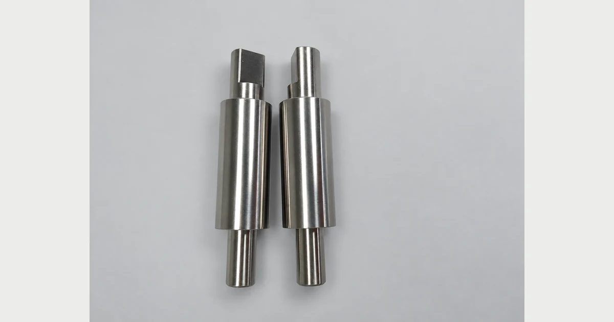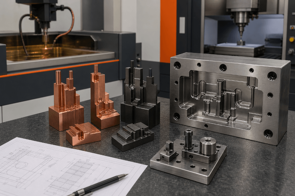
An EDM electrode is a production tool with its own geometry, material, datum structure, identification and process plan. It is not simply a positive copy of a mold cavity. The electrode must be designed around the selected sinker EDM technology, discharge conditions, programmed orbit, polarity, wear strategy, flushing and required cavity surface.
The electrode also has to survive manufacturing and handling before it reaches the EDM machine. A thin graphite rib may provide excellent detail in the burn but chip during milling or transfer. A copper electrode may hold a sharp edge yet require more machining time and careful burr control. A stable result therefore depends on the complete system, from cavity definition to final inspection.
This guide explains how to plan, manufacture and control graphite, copper and copper-tungsten electrodes for sinker EDM. For the surrounding milling, turning and EDM capabilities, begin with Samshion’s CNC machining services.
What Is an EDM Electrode?
In sinker EDM, controlled electrical discharges occur across a small dielectric-filled gap between an electrode and an electrically conductive workpiece. Each discharge removes a minute amount of material. Repeated discharges reproduce the electrode’s shape in the workpiece with a process-dependent overcut.
The electrode does not physically cut the cavity like an end mill. However, its geometry, material and surface condition influence burn stability, wear, achievable detail and the work required to reach the final surface. The machine generator, dielectric system, flushing, servo response and programmed motion are equally important.
This distinction matters because the old article placed electrode manufacturing and EDM machine control in the same list. They are connected but different stages:
- Electrode engineering defines geometry, compensation, material, base and identification.
- Electrode manufacturing creates and inspects the electrode and its reference system.
- Sinker EDM programming selects technology, orbit, polarity, power settings, flushing and wear compensation.
- Cavity verification confirms the workpiece result against its drawing and mold function.
The electrode supplier should not claim one universal accuracy or finish. Capability depends on feature size, depth, electrode material, number of electrodes, machine condition, burn technology and measurement plan.
When Is a Form Electrode Used?
Sinker EDM is commonly used when conventional cutting tools cannot efficiently reach or create a feature. Examples include:
- Deep ribs and narrow cavity details
- Sharp internal features that cannot be produced by a rotating cutter
- Textures or details on hardened mold inserts
- Complex blind cavities
- Small local features requiring a dedicated tool shape
- Features where cutting force must be avoided
EDM is not automatically the best choice for every hard or complex part. Open pockets, accessible radii and through features may be faster to mill. Wire EDM may suit through profiles. The design for CNC machining guide helps compare access, tooling and setup before choosing a process.
Inputs Required Before Electrode Design
Begin with a controlled workpiece definition. Electrode design should not be released from an uncontrolled CAD screenshot.
Finished Cavity Model and Drawing
Identify the final cavity geometry, functional datums, surface requirements, texture zones and critical details. Confirm whether the model represents the finished steel condition or an intermediate machining state. If multiple inserts form one molding surface, define the relationships between them.
Workpiece Material and Condition
Record the exact steel, carbide or conductive alloy and its hardness or heat-treatment condition. The selected EDM technology and electrode material must suit the actual workpiece. A burn plan for pre-hardened mold steel may not transfer directly to a different alloy or carbide application.
Machine and Generator Technology
Electrode compensation cannot be separated from the target EDM machine. Identify the machine family, generator technology, available orbit cycles, electrode changer, C-axis requirements, dielectric system and approved technology tables. A parameter from one machine or electrode material should not be copied into another setup without validation.
Surface and Documentation Requirements
Define the target cavity surface, dimensional evidence, visual standard and any texture that follows EDM. If the cavity will be polished, textured or coated later, the EDM allowance and surface plan must support those downstream operations. Review related surface-finish selection principles before finalizing the specification.
Select the Electrode Material by Application
There is no perfect electrode material for every sinker EDM job. Material selection should consider electrode detail, wear behavior, achievable surface, machining cost, handling, flushing and available machine technology.
Entegris POCO notes that EDM graphite grades with apparently similar published properties can behave differently because their microstructure and manufacturing consistency differ. Its EDM Graphite Buyer’s Guide recommends specifying the exact grade and controlling substitution rather than buying only from a generic property table.
Graphite EDM Electrodes
Graphite is widely used for sinker EDM because it machines efficiently, is available in application-specific grades and can provide useful wear and metal-removal performance. It is light, which helps with large electrodes and automatic handling.
Graphite is not one material grade. Particle size, uniformity, density, strength, hardness, electrical resistivity and supplier consistency influence electrode machining and EDM performance. A coarse, nonuniform material may not retain fragile detail or produce the same finish as a fine-grain grade.
Graphite also creates conductive dust during machining. The process requires suitable dust extraction, machine protection, cleaning and handling practices. A chipped edge cannot be repaired by adjusting the sinker EDM program.
Use graphite when the selected grade, electrode geometry and machine technology provide an appropriate balance of:
- Detail retention
- Electrode wear
- Surface target
- Electrode machining time
- Handling strength
- Total cost per acceptable cavity
Copper EDM Electrodes
Copper provides high electrical and thermal conductivity and can produce fine detail and controlled surfaces in suitable applications. It is common in mold making, small electrodes and shops where the machine technology and internal standards are built around copper.
Copper behaves differently during electrode manufacturing. It is ductile and can form burrs, smear or deflect if tools are dull or the setup is weak. Thin features need enough support. Machining parameters, tool geometry, coolant and finishing strategy should be selected for the actual copper grade.
Copper is heavier than graphite, which matters for large electrodes, long overhangs and automatic changers. It can also require more machining time than graphite for some geometries. Evaluate the complete route rather than selecting it only because it looks capable of a sharp surface.
Copper-Tungsten and Copper-Impregnated Graphite
Copper-tungsten is selected for specialized applications that need a combination of conductivity, wear resistance and feature strength. It is harder and more difficult to machine than conventional copper or graphite, so grinding, wire EDM or carefully selected cutting tools may be required.
Copper-impregnated graphite is a different material system. It can be useful for fragile electrodes or demanding burn conditions, but it should not be treated as interchangeable with copper-tungsten. Confirm the exact commercial grade, material data and supplier recommendation.
Electrode Material Comparison
|
Selection factor |
Graphite |
Copper |
Copper-tungsten or specialty composite |
|
Electrode machining |
Efficient with suitable tools and dust control |
Requires burr, heat and deflection control |
More difficult; process may include grinding or EDM |
|
Handling |
Light but brittle and vulnerable to chipping |
Ductile and heavier |
Stronger in selected details but dense and costly |
|
Fine detail |
Grade dependent |
Suitable with controlled machining |
Useful for selected small or wear-sensitive features |
|
Surface capability |
Grade and machine technology dependent |
Common for controlled fine-finish work |
Application specific |
|
Main decision |
Exact grade, structure and wear performance |
Geometry, machining time and burn technology |
Technical need must justify material and manufacturing cost |
The table is a starting point, not a substitute for machine and material supplier data. Entegris explains that material choice should be evaluated by total cost, including burn stability, electrode wear, surface result, electrode fabrication and polishing, not only purchase price. See its discussion of EDM electrode total cost of ownership.
Design the Electrode as a Controlled Tool
Separate Roughing and Finishing Roles
A complex cavity may use different electrodes or different programmed roles. A roughing electrode prioritizes efficient material removal and safe clearance. A finishing electrode protects final geometry and surface. Semi-finishing may be useful when depth, wear or surface requirements cannot be achieved reliably in one transition.
Do not assume one electrode count for all cavities. The number depends on electrode material, workpiece, depth, detail, wear distribution, surface target and machine technology. Record each role in the electrode list.
Plan Undersize, Overcut and Orbit Together
The electrode may be manufactured smaller than the nominal cavity so the discharge overcut and programmed orbit can produce the target geometry. The required relationship is not one fixed “spark gap.” It depends on the machine technology, electrode and workpiece materials, discharge energy, surface target, polarity and orbit strategy.
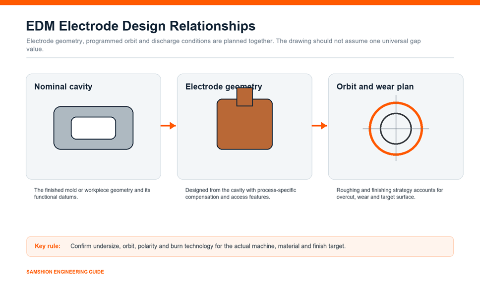
Control the following in the CAD/CAM and EDM setup records:
- Nominal finished cavity model
- Electrode CAD revision
- Electrode undersize or compensation method
- Roughing, semi-finishing or finishing role
- Programmed orbit or vector strategy
- Polarity and approved machine technology
- Expected wear and replacement plan
- Final verification method
Protect Thin Ribs and Fragile Details
Thin walls, ribs, letters and pins must survive electrode machining, inspection, cleaning, storage, setup and flushing. Increase local support where function permits. Use staged machining, suitable corner transitions and handling protection. If multiple fragile electrodes are needed, document their order and replacement criteria.
Include Flushing and Venting Strategy
Unstable debris removal can lead to arcing, pitting, slow burn and uneven wear. Electrode geometry may include flushing holes or channels when they do not damage the required cavity. External flushing, jump cycles and orbit strategy are alternatives. The correct solution depends on depth, area, geometry and machine technology.
Do not add flushing holes casually to a finishing electrode. Their witness effect, location and plug strategy must be evaluated.
Define Bases, Shanks and Orientation
The working detail needs a stable connection to the holder. Define the base, shank, reference faces, orientation and mounting method. Avoid an unnecessarily long, flexible extension. Provide holder clearance for the cavity and workpiece setup.
Permanent orientation marks and machine-readable IDs can reduce setup mistakes, but identification must not weaken the electrode or contaminate reference surfaces.
Manufacture Graphite Electrodes with Dust and Edge Control
Graphite electrode machining commonly uses CNC milling with sharp, suitable tooling and effective extraction. The exact cutter material and coating depend on the graphite grade, tool diameter, detail and production quantity.
Prepare Stable Stock and Datums
Use verified material of the specified grade. Establish stable datum faces and enough stock for the base and working geometry. Keep material certificates or grade records linked to the job when the application requires traceability.
Rough Before Finishing Fragile Details
Remove bulk material while the electrode has maximum support. Finish thin ribs and fine features after the surrounding load has been reduced. Avoid toolpaths that push unsupported details in a weak direction.
Control Tool Wear
Graphite is abrasive. A worn tool can change electrode size, edge condition and surface quality. Use controlled tool life, appropriate cutters and verification for critical details. The CNC cutting tool selection guide explains how substrate, geometry, holder and wear interact.
Manage Conductive Dust
Use equipment and extraction suited to graphite. Protect machine components and keep dust away from electrical cabinets, precision interfaces and unrelated inspection equipment. Clean the electrode without damaging fine features.
Manufacture Copper Electrodes with Burr and Heat Control
Copper electrode machining requires sharp tools, rigid workholding and stable chip evacuation. Smearing, built-up edge and burrs can alter a small feature even when the nominal toolpath is correct.
Use short tool reach where possible. Support thin features during roughing and finish them with a controlled strategy. Inspect burr-prone edges and intersections rather than relying only on a coordinate report. Grinding or polishing may be justified for selected surfaces, but uncontrolled manual bench work can change geometry and reduce repeatability.
When the electrode has complex milled details, apply the same access and fixture principles used in CNC milling. The difference is that the electrode will become a process tool, so its datum and identification must remain usable at the EDM stage.
Workholding and Datum Transfer
Electrode repeatability depends on the full chain from milling to inspection to sinker EDM. A pallet or standardized interface can reduce repeated alignment, but only when it is clean, controlled and verified.
Define:
- The electrode’s primary reference interface
- Orientation and rotation convention
- Holder or pallet ID
- Electrode zero and offset method
- Transfer procedure between machines
- Cleaning and interface inspection
- Maximum allowed overhang or mass for the holder system
Do not advertise “sub-micron repeatability” unless it is supported by the exact interface, operating conditions, measurement method and current capability evidence. Our CNC fixturing guide explains why locating, clamping and datum transfer must be treated as a process chain.
Makino’s discussion of reliability in die-sinking EDM emphasizes that graphite materials that look similar can differ in structure and EDM behavior. That principle reinforces the need to control both the electrode grade and the setup system.
Inspect and Register Every Critical Electrode
Inspection should match the feature and risk. A large roughing electrode does not need the same evidence as a fragile finishing electrode for a critical cavity detail.
Dimensional Inspection
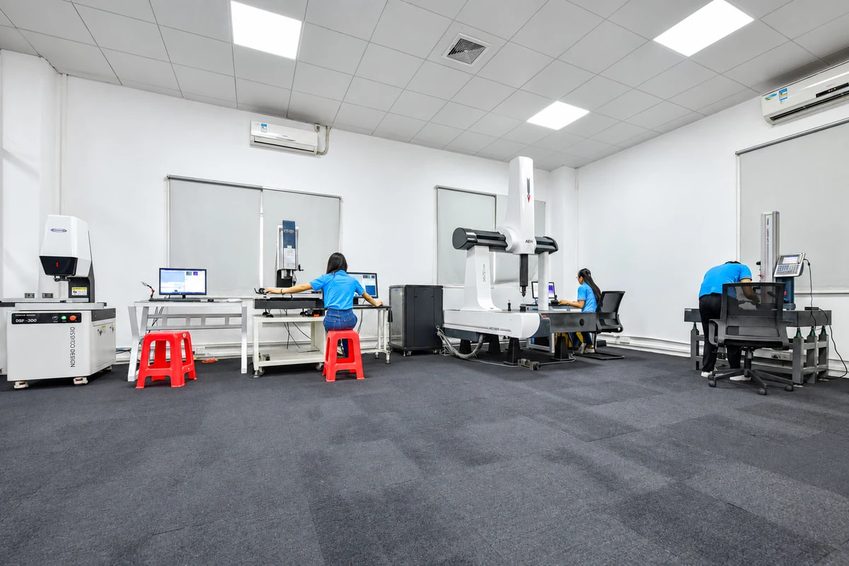
Use suitable methods for size, position, orientation, profile and runout. CMM, optical measurement, microscopes, height gauges and dedicated fixtures may be combined. Graphite edges require careful probing and handling. Copper burrs should be removed by a controlled method before final measurement.
The CNC machining inspection guide explains how to connect drawing characteristics to measurement methods and reports.
Verify the Datum Interface
Confirm the holder and electrode reference system, not only the working detail. Measure the relationship between the detail and the transfer interface so the EDM offset is meaningful.
Assign Unique Identification
Each electrode should be linked to:
- Job and workpiece insert
- CAD and CAM revision
- Electrode number and role
- Material and grade
- Holder or pallet
- Orientation
- Measured offset
- Target cavity location
- Status, including new, used, damaged or retired
An electrode register prevents the wrong tool, revision or offset from entering the machine.
Control the Sinker EDM Process
Electrode quality cannot compensate for the wrong burn technology. Use machine-approved technology for the actual electrode material, workpiece, surface target and geometry.
Polarity and Technology Selection
Polarity affects material removal and wear. The correct selection depends on electrode and workpiece materials, discharge regime and machine technology. Follow the machine manufacturer’s technology tables and validated shop standards rather than copying a universal recommendation.
Wear and Corner Protection
Electrode wear may be nonuniform. Corners, edges and small details can lose material faster than broad surfaces. Roughing and finishing roles, orbiting and replacement criteria should protect the final cavity.
Flushing and Debris Control
Stable dielectric conditions help remove debris and reduce abnormal discharges. Program jump cycles, flushing and orbit motion for the actual cavity. Excessive flushing pressure can deflect a fragile electrode, while insufficient debris removal can destabilize the burn.
Machine Capability Claims
Modern sinker EDM equipment includes thermal compensation, adaptive control and electrode changers. Mitsubishi Electric, for example, describes thermal-displacement control, scheduling and electrode-wear technology on its EA28V ADVANCE sinker EDM. Those capabilities are model and application specific. Do not transfer a manufacturer’s test result into a general promise for every Samshion project.
Verify the Cavity, Not Only the Electrode
The electrode can meet its drawing while the burned cavity misses its functional requirement because of wear, overcut, setup, thermal conditions or measurement error. Inspect the final cavity according to its drawing and mold function.
Verification may include:
- CMM or optical measurement of accessible geometry
- Mold shutoff and insert relationships
- Surface texture measurement
- Visual inspection for pitting or arcing
- Bench fit or blue-check where appropriate
- Mold trial and molded-part measurement
For injection mold programs, electrode and cavity control should connect to the broader rapid tooling process and final molding validation.
Common Problems and Corrective Questions
|
Problem |
Possible contributors |
Questions to investigate |
|
Electrode chips during milling or handling |
Fragile geometry, unsuitable graphite grade, weak support, tool wear |
Is the grade controlled? Can support or sequence change? |
|
Copper electrode has burrs or smeared edges |
Dull tool, unstable setup, poor chip evacuation |
Is the tool sharp and the feature supported? |
|
Burn is unstable or slow |
Debris, flushing, incorrect technology, excessive area |
Is the approved material and machine technology selected? |
|
Cavity is oversized |
Electrode compensation, orbit, wear, offset or measurement issue |
Are CAD revision, programmed orbit and measured offsets linked? |
|
Corner detail is lost |
Local wear, too few finishing electrodes, aggressive roughing |
Is wear distribution included in the electrode plan? |
|
Cavity has pits or abnormal marks |
Arcing, contamination, poor flushing or damaged electrode |
Is the dielectric and electrode condition verified? |
|
Repeat cavities differ |
Interface contamination, datum transfer, electrode variation, thermal state |
Are holders, offsets and inspection conditions controlled? |
Do not correct every problem by changing pulse settings. First identify whether the cause is material, electrode geometry, manufacturing, setup, flushing, programming or measurement.
EDM Electrode Manufacturing Workflow
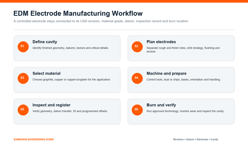
- Define the cavity. Confirm finished geometry, datums, material, texture and critical details.
- Plan the electrode system. Assign roughing and finishing roles, compensation, orbit, flushing and access.
- Select the material. Choose the exact graphite, copper or specialty grade for the application.
- Manufacture and prepare. Control cutting tools, dust or chips, bases, orientation and handling.
- Inspect and register. Verify working geometry, datum transfer, ID and programmed offsets.
- Burn and verify. Use approved machine technology, monitor wear and inspect the finished cavity.
How to Reduce Total Electrode and EDM Cost
Lowest electrode purchase price does not necessarily create the lowest cavity cost. Evaluate:
- Electrode material and machining time
- Number of roughing and finishing electrodes
- Cutting-tool wear
- Inspection and registration effort
- Holder and setup utilization
- EDM burn time and stability
- Electrode wear and replacement
- Cavity polishing and correction
- Scrap and schedule risk
Cost can sometimes be reduced by milling more open geometry and reserving EDM for inaccessible details. Other savings come from reusing standardized bases, improving electrode lists, controlling graphite grades and preventing revision mistakes. Do not advertise a fixed percentage without comparing the actual alternatives.
Information to Send for an EDM Electrode Review
Provide:
- Finished cavity CAD model and drawing
- Workpiece material and hardness
- Critical geometry and surface target
- Available sinker EDM machine and technology family
- Preferred electrode material or approved alternatives
- Required quantity and replacement plan
- Holder or pallet interface
- Inspection and documentation requirements
- Mold-trial or final acceptance plan
Samshion can review the relationship between cavity geometry, electrode material, CNC manufacturing, datum transfer and sinker EDM strategy. Upload your CAD files for a manufacturing quote.
Frequently Asked Questions
Is graphite always better than copper for EDM electrodes?
No. The choice depends on feature strength, surface target, machining time, wear behavior, machine technology and total cost. The exact graphite grade also matters.
How much smaller should an EDM electrode be than the cavity?
There is no universal value. Electrode geometry, discharge overcut and programmed orbit are planned together for the machine, electrode material, workpiece, roughing or finishing role and surface target.
Does every cavity need separate roughing and finishing electrodes?
Not always. Electrode count depends on geometry, depth, wear, material, surface and machine technology. Complex or critical cavities may require roughing, semi-finishing and finishing roles.
Can a CMM inspection of the electrode guarantee the cavity result?
No. It confirms selected electrode characteristics and datum relationships. The final cavity also depends on burn technology, orbit, wear, setup, flushing and workpiece conditions, so it requires its own verification.
Why do graphite electrodes chip?
Possible causes include unsuitable grade, fragile geometry, worn cutting tools, poor toolpaths, weak support, handling damage and incorrect cleaning. The fracture location and process history should be reviewed before changing the design.
When is copper-tungsten appropriate?
It is used for selected small, wear-sensitive or difficult applications where its conductivity and wear behavior justify higher material and manufacturing cost. Confirm the application with the material and machine technology supplier.