Wire electrical discharge machining can produce accurate through profiles in hardened steel, carbide and other electrically conductive materials. The process also has failure modes that are easy to misdiagnose. A witness mark near the start point may involve the lead-in path, discharge transition, flushing or skim strategy. An undersized corner may reflect the physical wire path, wire lag, the programmed control mode or an impossible drawing requirement. A part that moves after cutting may be releasing residual stress rather than responding to excessive EDM heat.
For this reason, wire EDM troubleshooting should not begin by copying one offset from another job. It should begin with a clearly defined defect and a controlled review of the drawing, material, setup, approved machine technology and inspection result. This guide provides that process for entry marks, corner errors, deformation, top-to-bottom variation, unstable cutting, slug control and fine die features.
For the broader process context, review Samshion’s CNC machining services and the complementary EDM electrode design and manufacturing guide. The second guide focuses mainly on electrodes for sinker EDM, while this article focuses on a continuously moving wire electrode and through-cut profiles.
What Wire EDM Troubleshooting Should Control
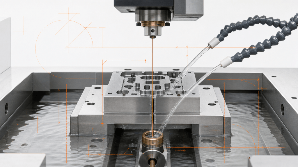
Wire EDM uses controlled electrical discharges between a moving wire electrode and a conductive workpiece in a dielectric environment. The wire does not contact the part as a saw would. The final contour results from the programmed wire centerline, the discharge gap, the behavior of the wire between the guides and the machine’s control strategy.
A good troubleshooting process must therefore control more than a nominal X-Y path. It should connect six elements:
- Product requirement: nominal geometry, tolerance, corner radius, taper, surface and functional datum.
- Material condition: grade, hardness, prior machining, heat treatment, residual stress and conductivity.
- Physical setup: clamping, support, part height, guide condition, nozzle position, flushing and slug retention.
- Machine technology: wire type and diameter, approved material and height table, discharge settings, servo control, tension and skim sequence.
- Programmed geometry: start hole, lead-in, entry and exit, offset, corner strategy, taper and tab location.
- Verification: measurement system, sampling locations, environmental control and documented result.
The target is not merely to make the machine finish the path. The target is to demonstrate that the released part satisfies its drawing after the relevant cutting, cleaning and stabilization steps.
Start With the Defect, Not a Favorite Parameter
Before changing a setting, define what is wrong. Statements such as “the corner is bad” or “the wire leaves a mark” are not enough. Record the defect’s location, direction, magnitude, surface appearance and repeatability. Note whether it occurs on the rough cut, after a skim pass, only at the top or bottom, or after the slug is released.
Confirm the Drawing Requirement
Check the nominal radius, profile tolerance, datum structure, taper direction and surface specification. A drawing may request an internal corner that cannot be produced with the selected wire and discharge condition. It may also apply a tight profile tolerance to a feature that is inspected from a different datum than the setup uses. Resolve these conflicts before tuning the machine.
The design for manufacturability guide explains how drawing requirements, tool access and process capability should be reviewed together.
Confirm How the Defect Was Measured
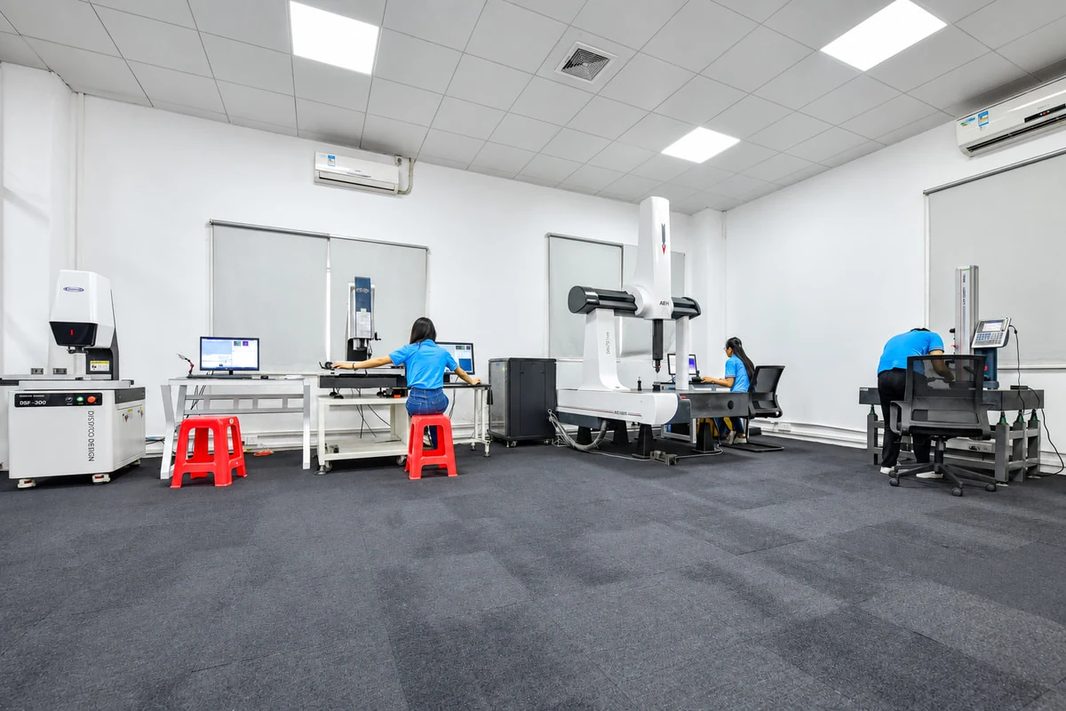
Use a measurement method that can resolve the feature. A surface scratch, an optical edge, a recast transition and a true dimensional error are different observations. For tall parts, inspect top, middle and bottom locations rather than reporting one average. For small corners, confirm the optical or probe method and its edge-detection rule. The CNC machining inspection guide provides a useful framework for matching the measuring system to the tolerance.
Establish a Baseline
Save the program revision, machine technology selection, wire lot or specification, workpiece condition, setup photos, nozzle positions, dielectric information and inspection result. Change one controlled factor at a time when practical. Without a baseline, several simultaneous changes may appear to solve the problem while hiding the actual cause.
Wire EDM Process Variables That Interact
Wire EDM variables are coupled. Increasing flushing pressure may improve debris removal but deflect a weak wire or disturb a small slug. Raising tension can improve straightness within the approved range but cannot compensate for worn guides or an unsuitable technology table. A larger number of skim passes does not automatically correct a rough cut that allowed the workpiece to move.
Wire and Wire Path
Wire material, coating, diameter, tensile behavior, cleanliness and feed condition influence stability. The wire-contact components, guides, tension system and feed path also matter. Inspect for contamination, wear, misalignment and damage according to the machine builder’s maintenance procedure.
Dielectric and Flushing
The dielectric controls the discharge environment and carries debris away from the cutting zone. Conductivity, filtration, temperature, nozzle distance, seal quality and part geometry influence this function. Poor flushing can create unstable discharge concentration, slow cutting, wire breaks, surface pits and top-to-bottom variation.
Modern machines may adapt power or cutting conditions when flushing is poor or the workpiece height changes. For example, UNITED MACHINING describes Spark Track and ISPS as systems that monitor discharge location and adapt cutting parameters. These functions are valuable, but they remain machine-specific tools rather than universal substitutes for a sound setup. See the manufacturer’s wire-cutting EDM technology overview.
Discharge, Servo and Tension Control
The selected machine technology coordinates discharge energy, pulse behavior, feed, servo response, wire tension and other variables for the actual wire, workpiece material, height and finish target. Begin with the machine builder’s approved table. Do not treat an isolated setting from another brand or material as a validated recipe.
Workpiece and Setup
Material stress, thickness variation, interrupted surfaces, start holes, prior heat treatment, clamping and support can dominate the result. A stable program cannot prevent a slender part from moving when a stressed section is released. A consistent datum and appropriate support are especially important when the part will be unclamped, flipped or moved between operations. Review the CNC fixturing and datum-transfer guide when multiple setups are involved.
How to Reduce Wire EDM Entry and Exit Marks
An entry or exit mark is a local transition near the point where the wire approaches, joins or leaves the finished contour. It may appear as a dimple, witness line, local profile deviation or surface change. Its cause depends on whether the cut is an open external profile, a closed internal contour or a cut requiring a retained slug.
Choose the Start Location Deliberately
Place the transition away from sealing surfaces, precision fits, thin tips and cosmetically critical faces when geometry permits. On an internal contour, the start hole and approach path should provide enough room for stable threading, flushing and transition into the finished path. On an external profile, consider whether the approach can begin in sacrificial stock or a noncritical region.
Use a Geometry-Specific Lead-In
A straight radial lead-in may concentrate the transition at one location. An arc, tangential approach or blended path may reduce the local change for suitable geometry. The correct path depends on contour direction, available stock, start-hole location, offset, corner requirements and the machine’s entrance-control functions.
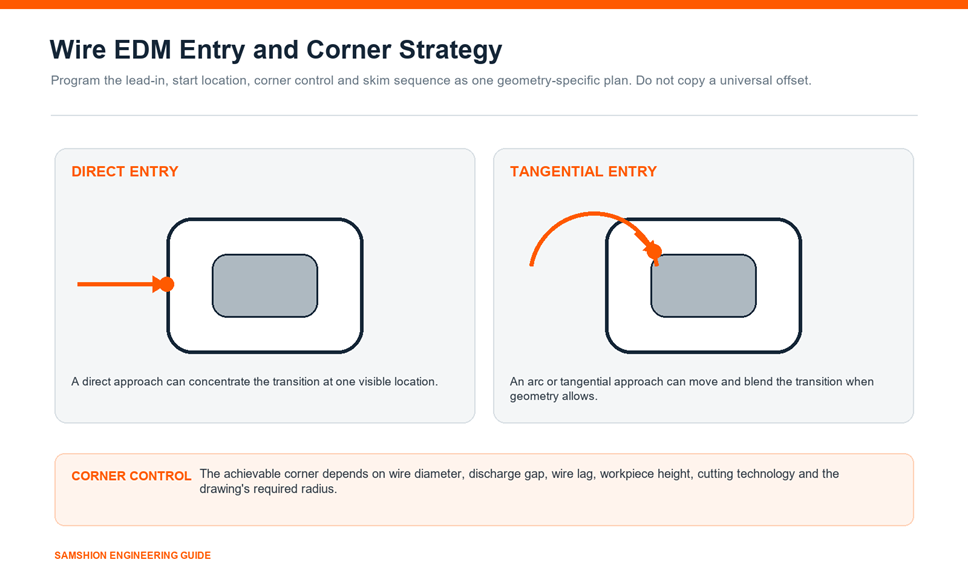
Do not publish one compensation such as a fixed value for a particular wire diameter as a universal rule. The effective discharge gap and transition behavior change with wire type, workpiece, thickness, roughness target, pass number and machine technology.
Separate Rough and Skim Objectives
The rough cut establishes the initial profile and may leave greater wire lag, surface roughness and stress-release movement. Skim passes use different technology to refine geometry and surface. Their offsets and directions should follow the machine builder’s strategy and the actual stock remaining. Repeating a skim pass without understanding the remaining error may waste time or reproduce the same problem.
Mitsubishi Electric describes dedicated entrance and corner controls in its official wire-cut EDM systems catalog. This is evidence that transition control is a coordinated machine function, not proof that one value applies to every wire EDM.
How to Improve Wire EDM Corner Accuracy
Corner accuracy is affected by programmed geometry, wire radius, discharge gap, wire lag, feed behavior, workpiece height, flushing and machine control. The wire spans between upper and lower guides, so it can bow or lag during a direction change. A sharp change in motion can create a different error from a long straight cut.
Recognize the Physical Radius Limit
The centerline of a cylindrical wire cannot follow an infinitely sharp internal corner while maintaining a finite discharge gap. The achievable internal radius must be compatible with the wire diameter and the selected cutting condition. If the drawing requires a smaller radius, options may include a smaller approved wire, a design change, a relief feature, a different EDM process or a secondary operation.
Treat Internal and External Corners Differently
At an internal corner, the available radius and discharge concentration influence the result. At an external corner, wire lag and path control can round or overcut the tip. Machine-specific corner technology may modify feed and discharge behavior for radius, angle and thickness. Use the correct corner classification and verified technology rather than applying one correction to every turn.
Verify the Complete Height
A top-view optical result can hide a middle-section bow in a tall workpiece. Measure at relevant heights or use a method that captures the full profile. If the top and bottom agree but the middle does not, investigate wire straightness, rough-cut behavior, flushing and the selected tall-part technology before changing a simple X-Y offset.
Makino’s BellyWIZARD technology overview explains that center-span bow can originate during the initial rough cut and that adaptive compensation considers workpiece height, wire wear and wire lag. The specific function belongs to Makino equipment, but the underlying diagnostic lesson applies broadly: identify where through the height the error occurs.
How to Control Wire EDM Deformation and Residual Stress
Wire EDM is a thermal erosion process, but large movement after profile release is often dominated by residual stress already present in the blank. Stress may come from rolling, forging, heat treatment, welding, rough machining or an uneven stock condition. Removing a closed profile or a large slug changes the force balance and allows the material to move.
Separate Thermal Surface Effects From Part Movement
A small heat-affected surface layer and recast condition are different from global part warpage. If the entire profile opens, closes, twists or changes after release, review the material history, geometry and stock-removal sequence. Do not assume that reducing discharge energy alone will correct stress redistribution.
Plan Blank Preparation
For sensitive tool-steel components, rough-machine the blank symmetrically where practical, allow adequate stock, perform the specified heat treatment and stabilization process, and finish critical datums before wire EDM. The exact stress-relief or tempering cycle belongs to the material and heat-treatment specification. A machining supplier should not claim that one cycle is always required for every alloy.
Use Staged Release and Support
Tabs, bridges or an intentionally retained section can keep a delicate profile supported during rough cutting. A later operation can release the part after the geometry is stabilized and inspected. The tab location must avoid critical surfaces and allow controlled removal. For highly sensitive parts, a rough cut followed by relaxation, re-datum and finish cuts may be appropriate, but it must be validated for the drawing and material.
Inspect in the Released Condition
Measurements taken while the part is heavily clamped can hide movement. Define whether the specification applies in a free state, a restrained assembly state or a functional fixture. Record the condition in the inspection plan.
Thick Workpiece and Tall-Section Variation
Tall workpieces can show taper, barrel, hourglass, bow or different dimensions at the top and bottom. These errors should not be compressed into one generic “taper compensation” value.
Diagnose the Error Shape
Measure several heights and compare them with the programmed taper and drawing. A consistent top-to-bottom slope suggests a different cause from a center bulge. Also note whether the error changes with cutting direction, surface interruption or nozzle position.
Check the Setup Before Compensation
Confirm workpiece height, flatness and orientation. Inspect guide alignment, nozzle condition, nozzle distance, wire tension system and dielectric performance according to the machine manual. Verify that fixtures do not block flushing. For uneven or interrupted heights, use a machine technology intended for that condition if available.
Makino’s High-Energy Applied Technology overview discusses cutting in poor-flushing, nonsealed-nozzle and varying-thickness conditions. Its published performance figures describe controlled applications on Makino equipment, not a general tolerance promise for every supplier or part.
Use the Correct Machine Technology Table
Select the approved combination of material, height, wire, roughness and pass count. If a dimensional correction remains, base it on measured evidence from the actual setup and document the revision. Reinspect top, middle and bottom after the change. A correction without a repeatable baseline can conceal guide wear or unstable flushing.
Surface Lines, Pits and Unstable Cutting
Lines, pits, arc damage, frequent short circuits, slow cutting and wire breaks can share related causes. Debris concentration, unsuitable conductivity, contaminated guides or contacts, incorrect technology, poor nozzle conditions, an interrupted surface or damaged wire may destabilize the discharge.
Review the Surface Pattern
A line that repeats at a consistent height may point toward a change in flushing or geometry. Random pits may suggest unstable discharge or contamination. A transition visible only at the entry point requires a different investigation. Record magnified images with location and direction instead of using a generic “tool mark” label.
Check Consumables and Maintenance Items
Inspect the wire path, contacts, guides, rollers, filters, nozzles and dielectric system according to the manufacturer’s schedule. Replace or clean components only with approved procedures. Maintenance evidence is more useful than assuming that extra skim passes will erase every defect.
Define the Required Surface
Wire EDM can produce a controlled surface without conventional cutting burrs on the eroded contour, but it should not be advertised as universally burr-free or ready for every final application. Start-hole edges, retained tabs, slug removal, handling and downstream processes can create their own conditions. The required roughness, recast acceptance and cosmetic standard should be stated on the drawing or quality plan. For broader choices, consult the surface-finish selection guide.
Slug Retention, Tabs and Cut-Off Strategy
An uncontrolled slug can drop, tilt, pinch the wire, damage a nozzle or interfere with unattended machining. Small loose pieces can also create safety and cleanliness problems. Plan slug control before releasing the program.
Possible methods include programmed tabs, sacrificial bridges, mechanical support, dedicated fixtures, magnets for suitable ferromagnetic work, or approved adhesive methods. Each method has limits. Adhesive can contaminate the dielectric or fail under heat and water. A magnet can affect debris or access. A tab can distort a thin part or require secondary removal.
Choose the method from slug mass, orientation, machine access, material, surface requirement and automation plan. Define how the slug and tab will be removed, how the edge will be finished and how the final profile will be inspected. Never reach into an active machine to catch a falling slug.
Small Radii, Fine Slots and Terminal-Die Features
Fine punches, die openings, narrow slots and terminal-die features combine corner, clearance, taper and strength requirements. The punch and die are not simply identical male and female profiles. Their relationship must come from the product material, stock thickness, cutting clearance, intended break and burnish, wear plan, stripping condition and toolmaker’s design standard.
If a punch and die share a controlled geometry, define which component is nominal, where clearance is applied and how taper or relief is oriented. Do not rely on an unexplained angle formula copied from another tool. The CAD models, drawing revisions and inspection reports should identify the relationship explicitly.
For prototype or bridge tooling decisions, the rapid tooling process can help place wire EDM within the wider toolmaking route.
Inspection Plan for Wire EDM Parts
An inspection plan should be written before cutting begins, especially for tall sections, sharp corners, matched tool components and stress-sensitive profiles.
|
Requirement |
Recommended evidence |
Common mistake to avoid |
|
2D contour or profile |
Vision system, CMM scan or approved contour method tied to drawing datums |
Reporting only one local dimension |
|
Small corner radius |
Calibrated optical or profile measurement with defined edge rule |
Judging from a screenshot or uncalibrated magnification |
|
Tall-part straightness |
Measurements at top, middle and bottom or a full-height method |
Checking only top and bottom |
|
Taper |
Defined height locations and sign convention |
Applying a correction before confirming orientation |
|
Surface condition |
Roughness measurement and documented visual standard where required |
Calling every line a dimensional defect |
|
Released-part deformation |
Free-state or specified restraint inspection after release |
Measuring only while heavily clamped |
|
Matched punch and die |
Separate component reports plus assembled or functional relationship |
Assuming shared nominal geometry proves clearance |
Inspection should use controlled datums, calibrated equipment and an agreed sampling plan. Samshion’s quality assurance and inspection systems describe the broader documentation framework for manufactured parts.
Wire EDM Troubleshooting Matrix
|
Symptom |
Likely contributors to investigate |
First controlled checks |
Verification |
|
Entry dimple or witness mark |
Lead-in geometry, transition control, offset sequence, flushing, start location |
Compare rough and skim results; review entry path and approved entrance technology |
Profile and surface at the entry location |
|
Rounded or inaccurate corner |
Physical radius limit, wire lag, corner classification, height, technology |
Confirm drawing radius, wire system, part height and corner-control selection |
Optical or profile result through relevant height |
|
Part opens or twists after release |
Residual stress, asymmetric roughing, clamping, tab sequence |
Review material history, blank preparation and released-state behavior |
Measure free state after staged release |
|
Top-to-bottom size difference |
Taper setup, guide alignment, flushing, tension, height input |
Check orientation, guide/nozzle condition and technology table |
Measure top, middle and bottom |
|
Center bow or belly |
Rough-cut wire behavior, flushing, wire lag, tall-section technology |
Map error through height and compare rough versus skim |
Full-height straightness profile |
|
Pits or unstable surface |
Debris, conductivity, contacts, guides, wire, discharge stability |
Check dielectric, consumables, maintenance and technology |
Magnified surface record and roughness if specified |
|
Frequent wire breaks |
Poor flushing, discharge concentration, wire path, incorrect settings, interrupted geometry |
Inspect wire path and nozzles; use approved technology for geometry |
Stable cut log and accepted surface |
|
Slug movement or collision |
Unsupported slug, weak tab, poor cut order, fixture interference |
Review mass, orientation, tab and support method |
Safe release plus final edge inspection |
The table is a diagnostic starting point. It does not replace the machine manual, material specification or drawing.
A Controlled Wire EDM Troubleshooting Workflow
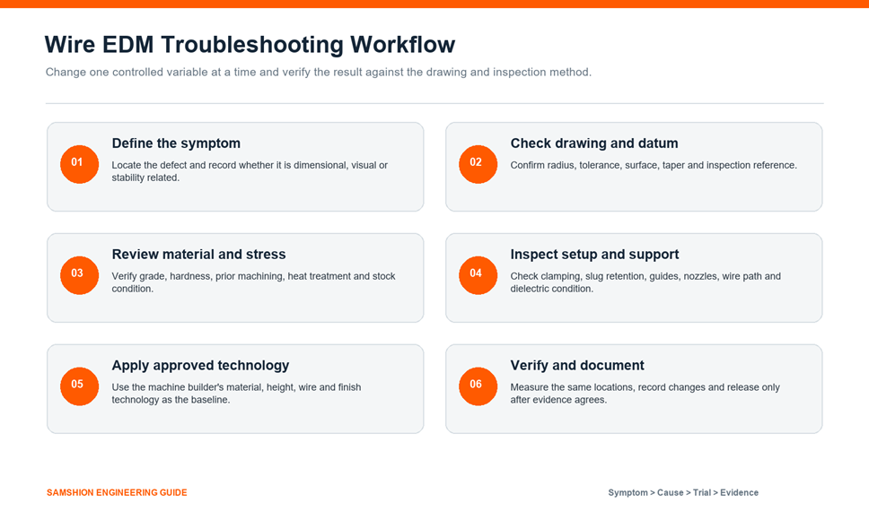
- Define the symptom. Record its location, direction, magnitude, appearance, pass number and repeatability.
- Check the drawing and datum. Confirm the actual radius, profile, taper, surface and released-state requirement.
- Review material and stress history. Verify grade, hardness, stock form, prior machining and heat treatment.
- Inspect setup and machine condition. Check support, slug plan, guides, nozzles, wire path, dielectric and maintenance status.
- Apply approved technology. Use the machine builder’s table for the actual material, height, wire and finish, then change one factor with a stated reason.
- Verify and document. Measure the same locations with the same method, record the result and preserve the successful revision.
This sequence prevents a common error: changing several offsets and power settings until one part looks acceptable, without learning whether the result can be repeated.
DFM Information to Send for a Wire EDM Quote
Provide enough information for the supplier to identify process and inspection risks before production:
- 3D CAD model and controlled 2D drawing
- Material grade, stock form and hardness or heat-treatment condition
- Quantity and revision level
- Critical datums, profile tolerances and corner radii
- Part thickness and any varying-height or interrupted surfaces
- Required taper, relief or punch-and-die relationship
- Surface roughness, recast or cosmetic requirement where relevant
- Start-hole restrictions and permitted tab or witness-mark locations
- Free-state or restrained inspection condition
- Required inspection report, sampling plan and traceability
- Downstream grinding, polishing, coating or assembly requirements
Upload these items through the CAD file engineering review so the cutting and inspection route can be evaluated together.
Frequently Asked Questions
What causes a mark where wire EDM enters the contour?
The mark can come from the lead-in geometry, start location, discharge transition, flushing, offset sequence or the difference between rough and skim behavior. Record when it appears and review the machine’s approved entrance-control strategy. Do not assume one fixed compensation value applies to every job.
Can wire EDM make a perfectly sharp internal corner?
No physical wire-and-gap system creates an infinitely sharp internal corner. The achievable radius depends on wire diameter, discharge condition, machine control, workpiece height and tolerance. If the drawing requires a smaller radius, evaluate a smaller approved wire, relief geometry, another EDM method or a design change.
Does wire EDM itself cause part deformation?
Wire EDM creates a thermal surface condition, but large movement after release often comes from residual stress in the blank, heat treatment or earlier machining. Diagnose the material history, geometry, clamping and release sequence before treating the issue as a discharge-energy problem.
Why are the top and bottom dimensions different on a thick part?
Possible contributors include taper setup, guide alignment, flushing, wire tension, wire lag, nozzle position, height input and unsuitable technology. Measure top, middle and bottom to identify the error shape before applying compensation.
How many skim passes are required?
There is no universal number. It depends on the rough-cut condition, material, height, wire, target geometry, surface and machine technology. Use the builder’s approved sequence as the baseline and verify the result with inspection evidence.
Is a wire EDM surface automatically ready to use?
Not always. The required roughness, recast condition, visual standard, tab-removal edge and downstream finishing determine acceptance. A wire-cut contour may avoid conventional cutting burrs, but start holes, tabs, handling and later operations can still require attention.
Conclusion
Reliable wire EDM troubleshooting is a controlled engineering activity, not a search for one universal offset. Define the defect, confirm the drawing and datum, understand the material history, inspect the setup, use approved machine technology and verify the released part. This approach makes entry marks, corner errors, deformation, thick-section variation and unstable cutting easier to diagnose and less likely to return.
For a project review, upload your CAD files for an engineering review together with the material condition, critical tolerances, surface requirements and inspection expectations.