Introduction: When Perfect Parts Refuse to Assemble
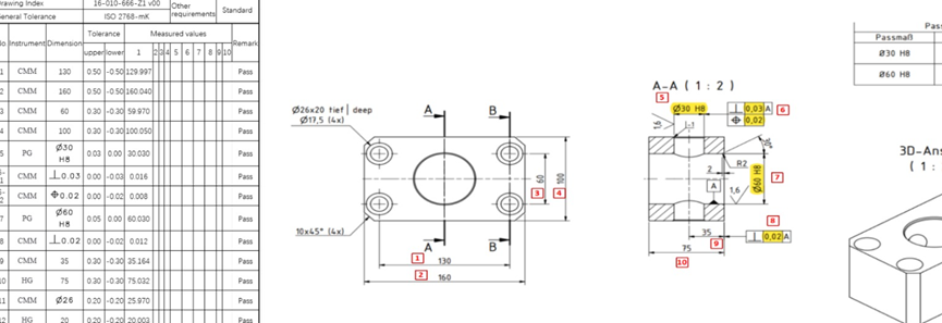
I believe as customers, you may have encountered similar ‘nightmares’. You have received a batch of CNC prototypes, and the shipping report looks flawless. Each key dimension is highlighted in green, each hole is precisely positioned according to the modeling, and each individual component is strictly within its specified tolerance range. Your supplier even provided a report before shipment, and you agreed to the shipment request.
Then comes the moment of truth: the assembly.
If you try to install the machining bracket into its custom housing or slide the precision pin into the housing, it will get stuck. Or worse, the components are too loose and make creaking sounds, damaging the integrity of the structure. You carefully check the printed copies and re measure the parts – everything is perfect. However, the system did not function properly. Why?
The Hidden Saboteur: Tolerance Stack-Up
This prototyping nightmare is almost always the result of tolerance stack-up. It is one of the most underestimated risks in CNC machining, occurring when the cumulative effect of individual part variances adds up to a total deviation that exceeds the assembly’s functional limits.
In a complex project, a single ±0.05 mm variance might seem negligible. However, when 3 such parts interface in a single assembly, that tiny error can balloon into a 0.15 mm disaster. Without a proper worst-case analysis or statistical distribution strategy, your perfect parts are destined for conflict.
The Real Cost of Dimensional Drift
In the high-stakes world of R&D, tolerance stack-up is not just a technical glitch—it can cause the butterfly effect, resulting in a waste of money and time. When the dimensions of the components do not match, the resulting chain reaction may cause chaos throughout the entire product cycle.
Expensive rework and scrapped material: High end industry prototypes often use precious metals or advanced engineering plastics, which can only become expensive waste for recycling.
Crushed project timelines: Every hour spent diagnosing assembly issues and waiting for revision-B prototypes is an hour lost in the race to market.
Missed launch windows: In competitive industries, a two-week delay in the prototyping phase can mean missing a critical trade show or a seasonal retail window.
At Samshion Rapid, we do not just cut to print. We understand how these dimensions interact. In this blog, we will explore the root causes of stack-up and—more importantly—how you can optimize your designs to ensure that perfect on paper means perfect in your hands.
What Is Tolerance Stack-up? (And Why Does It Happen Silently?)
In the field of high precision manufacturing, 100% absolute perfection is actually impossible. Every processing technology has its inherent variability or uncontrollability, and understanding how these interact is the difference between a functional product and expensive scrap metal.
The Definition of Tolerance Stack-Up
In mechanical design, tolerance stack-up refers to the cumulative effect of individual part deviations within an assembly. While a single dimension holding a ±0.05 mm tolerance seems safe on its own, parts rarely exist in isolation. But when parts are connected to each other through multiple feature surfaces, , these tiny errors stack like building blocks. If the total accumulation exceeds the designed clearance, the assembly will seize or fail.
Linear vs. Geometric Stack-Up
Linear Stack-up (1D)
This involves dimensions along a single straight line. For example, three brackets mounted side-by-side in a custom enclosure. The total width is simply the algebraic sum of the individual dimensions and their tolerances.
Geometric Stack-up (GD&T)
This is far more complex and involves two-dimensional or three-dimensional relationships such as orientation, profile, and location. A hole might be within its diameter specification, but if its position is off by 0.1 mm or its axis is tilted due to a parallelism error, a bolt will not pass through multiple mating plates.
Worst-Case Tolerance Accumulation Explained
Worst-case analysis is a conservative engineering approach. It assumes that every single component in the assembly chain is manufactured at its extreme limit, either maximum material condition or minimum material condition, and in the same direction.
Why Multi-Part CNC Assemblies Are Especially Vulnerable
CNC-machined components, such as electronic housings and industrial shelf brackets, are particularly sensitive to tolerance stack-up for several technical reasons:
Material Rigidity
Unlike injection-molded plastics that can flex to accommodate a poor fit, metal CNC parts are uncompromising. If the math does not work, the metal will not move.
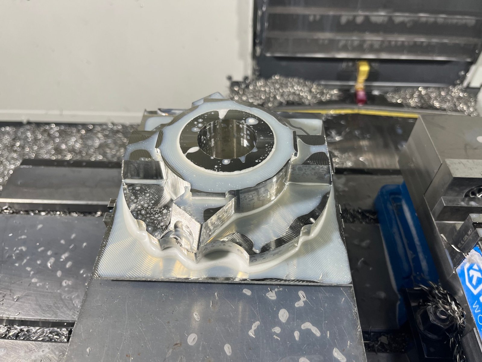
Setup Errors
Complex CNC parts often require multiple setups, including flipping the part. Each setup introduces a minute coordinate shift that contributes to the overall stack-up during final assembly.
Surface Texture Interaction
Under high clamping force, even the microscopic peaks of an as-machined surface with Ra 3.2 μm roughness contribute to the dimensional loop. When stacking five or six plates, these microns add up quickly.
Why CNC Prototypes Are More Prone to Tolerance Issues
In the R&D phase, prototypes often face greater assembly challenges than final production parts. This is Jeff Zhu, the quality manager of Samson, summarizing based on his experience. This is not necessarily due to a lack of machine precision, but rather the unique variables inherent in the prototyping environment.
Prototype vs. Mass Production Tolerances
One-off Machining vs. Process Control
Mass production benefits from dialing in the process through pilot runs and statistical process control (SPC). Prototypes, however, are often one-offs. The operator does not have the opportunity to fine tune the accuracy through multiple loops, and may only have a few small chances.
Tool Wear and Setup Variations
In high-volume runs, tool wear is predictable and compensated via sensors. In prototyping, different machines, varied tool ages, and manual setup changes introduce hidden variations that are harder to track.
Design Assumptions vs. Machining Reality
Over-Idealized CAD Dimensions
A CAD model is a perfect mathematical environment where 10.00 mm is absolute. In the physical shop, material properties such as internal stress and tool deflection create minute deviations that the CAD environment fails to predict.
Missing Datum References and Unclear GD&T
This is the number one cause of prototype failure. Without clear datum feature symbols, the machinist may use a different reference point for setup than the one used for assembly. The part may be within tolerance on individual features, but the relationship between them will be flawed.
Multiple Processes, Multiple Errors
The Complexity Chain
Some complex assembly prototypes may require CNC milling, bending, grinding, welding, and surface treatment.
Tolerance Layering
Every time a part moves from one machine to another, for example from a mill to a press brake, a new layer of tolerance is introduced. If a sheet metal bracket is welded to a CNC-machined housing, the heat-affected zone can warp the precision-machined faces, causing the stack-up to fail even if the initial milling was perfect.
What Are the Typical Symptoms of a Tolerance Stack-up Failure?
Identifying a stack-up issue early can save weeks of troubleshooting. If your CNC prototypes exhibit these red flags during the first build, your dimensional loop likely needs a redesign.
Holes That Almost Line Up
It is the ultimate engineering frustration: you can see light through the holes, but the bolt simply will not pass through. This occurs when the cumulative positional tolerance of multiple mating parts shifts the clear opening until it is smaller than the fastener diameter.
The Result:
Engineers are forced to oversize the holes, which often compromises the alignment precision and structural integrity of the assembly.
Shafts That Bind or Seize During Assembly
In precision motion assemblies such as bearings or slides, stack-up failures manifest as unintended interference. Even if the shaft and the housing are both within print, a worst-case scenario where one is at the upper limit and the other at the lower limit can eliminate the necessary running clearance.
The Result:
The shaft may become stuck and unable to slide, or completely jammed under pressure, resulting in complete damage to expensive precision machined parts.
Excessive Vibration or Noise After Assembly
Not all stack-up issues lead to parts being too tight; some create assemblies that are too loose. When tolerances gradually accumulate to the least ideal state, the gaps inside the product will exceed the design intent.
The Result:
This looseness leads to excessive vibration, rattling, or gear noise during operation. In high-speed CNC components, this results in rapid wear and premature fatigue failure. If there is a problem with this component, it may even cause dangerous accidents.
Assemblies Requiring Force, Shims, or Manual Adjustment
The clearest sign of a stack-up failure is the presence of field fixes on the assembly floor. If technicians are reaching for rubber mallets to force parts together, shims to fill unexpected gaps, or files to manually trim edges, the design is in trouble.
The Result:
Manual adjustments are not scalable. A prototype that requires hand-fitting is a warning that mass production will be plagued by high scrap rates and inconsistent quality.
Should You Use Worst-Case or Statistical Tolerance Analysis?
When dealing with tolerance accumulation, Samshion’s engineers usually have two methods. The selection method will directly determine the qualification rate of the prototype and the final production cost.
Worst-Case Tolerance Analysis
This is the most traditional tolerance accumulation calculation method. Add together the most extreme tolerances of each assembly and calculate the maximum error value. Of course, in the CNC machining process, this simple direct accumulation will undoubtedly increase precision requirements and labor costs.
When to use worst-case analysis:
Despite its conservatism and high manufacturing costs. But when we manufacture parts that are related to life safety, such as medical implants or certain components of automobiles, even a risk of interference of one in ten thousand is unacceptable.
Statistical Tolerance Analysis
Using statistical methods to calculate, because the probability of multiple parts reaching the limit tolerance at the same time is very small.
Basic concept of RSS (Root Sum Square):
This method assumes that the dimensions of the parts are usually normally distributed (bell shaped curve).
Qualified Size but Failed Assembly? The Critical Role of Geometric Constraints
Why ± dimensions alone are not enough
Samshion’s engineering manager Benny pointed out that traditional positive and negative tolerances can only control the size of features, but cannot effectively control the geometric relationships of features. He took our prototype example as an example, although the diameter of the tapped hole is completely qualified, if it deviates from the matching reference plane by 0.5 °, screws and rivets cannot penetrate.
Datums, position, flatness, and concentricity explained
When manufacturing prototypes, we have four core principles to control cumulative tolerances:
Datums: The starting point for all measurements. Without consistent datums, the machinist and the inspector may measure from different surfaces, introducing “hidden” stack-up errors.
Position: The ultimate solution for “misaligned holes.” It defines exactly where a feature (like a hole or slot) should be relative to the datums.
Flatness: In multi-plate assemblies (like stacked sheet metal), if the first plate isn’t flat, every subsequent layer “amplifies” the deviation, leading to massive misalignment at the end of the stack.
Concentricity: Ensures two rotating features share the same center axis, preventing binding in bearing and shaft assemblies.
How to Design CNC Prototypes to Avoid Tolerance Stack-up
At Samshion Rapid, we believe the most effective way to handle tolerance stack-up is to design it out of the system before the first chip is ever cut. Here are the three core strategies we recommend during our design reviews.
Design for Assembly (DFA)
Functional vs. Cosmetic Tolerances
Not all dimensions carry the same weight. We encourage clients to use tight tolerances, such as ±0.02 mm, only for critical functional features like bearing seats, while using relaxed cosmetic tolerances, such as ±0.15 mm, for external profiles. This prevents noise from non-critical areas from skewing the overall tolerance loop.
Intentional Clearance Design
Never design size-on-size. If you design a 10.00 mm shaft to go into a 10.00 mm hole, physical reality will almost certainly ensure they never fit. At Samshion Rapid, our engineers review your CAD to ensure there is enough breathing room based on material properties and post-processing effects, such as coating thickness.
Proper Datum Strategy
Functional Datums Over Convenient Ones
Datums should reflect how the part sits in the final assembly. If two parts bolt together on a specific face, that face should be designated as Datum A.
Machining Sequence Awareness
The team at Samshion Rapid plans the machining sequence so that critical features linked by a tolerance stack-up are machined in the same setup whenever possible. This eliminates the errors introduced by flipping or re-clamping the part multiple times.
Reducing Part Count
Why Fewer Is Better
Every interface between two parts is a new opportunity for tolerance stack-up. If an assembly consists of four bolted brackets, there are three interfaces adding cumulative error to the system.
Monolithic Design
Where the budget allows, we use 5-axis CNC machining to consolidate multiple components into a single complex part. While the individual part cost may rise, the hidden costs of tolerance stack-up drop to zero. And it greatly eliminates the risk of failed prototypes.
The Samshion Rapid Advantage
When you send a project to Samshion Rapid, you are not just getting a machinist; you are getting a manufacturing partner. We perform a pre-machining DFM (Design for Manufacturability) review on every order to identify and eliminate potential tolerance stack-up issues before they ever reach the spindle.
Conclusion: Tolerances Define Whether Parts Merely Exist—or Actually Work
The quality of assembled parts cannot be solely reflected in the qualified labeling of individual part inspection reports. They need to prove it more in a precise assembly system.
CNC machining accuracy ≠ assembly success:
High end machine tools are only a prerequisite for producing parts with extremely precise dimensions, but if there are omissions and oversights during the design phase, these high-precision individual parts may still fail during assembly. Processing accuracy is the foundation, but tolerance logic is the soul of success.
Tolerance stack-up as a system-level problem, not a single-part issue:
We need to start from the entire assembly drawing and structure to eliminate the thinking of “isolated parts”. Reverse analyze the operation, transmission, linkage and other issues of the overall structure, and dismantle the impact of tolerances on it.
Final takeaway: tolerances should be engineered, not guessed:
If engineering design relies on intuition to annotate, it often destroys the design or leads to skyrocketing costs. Successful prototyping requires tolerances that are scientifically calculated through Worst-Case Analysis or statistical modeling.
At Samshion Rapid, we understand that every micron matters. We aren’t just your machinist; we are your technical partner. Do you need free DFM analysis? Please let us know.