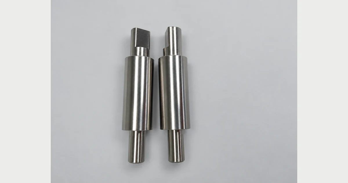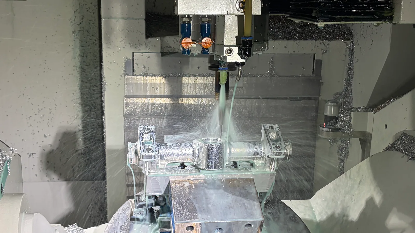
CNC machining is a manufacturing process that uses computer-controlled machine tools to remove material from a workpiece. In milling, turning and drilling, cutting tools shape metal or plastic stock into a component defined by a drawing or digital model. CNC stands for Computer Numerical Control.
For a customer ordering parts, the important question is how that digital design becomes a component that can be used or assembled. The model supplies the shape, but material, tolerances, tool access, workholding and finishing requirements determine how the part is manufactured and checked.
This guide explains the CNC machining process, the main machine types, material considerations and the information needed to order a part. It also uses a CNC-machined ABS assembly from a SAMSHION project to show how separate components relate to a finished assembly.
How CNC machining turns a drawing into a part
CNC machining follows a prepared program rather than relying on an operator to guide every cutting movement manually. The program controls movements and operating instructions such as spindle speed, feed rate and tool changes. People still plan the process, prepare the setup and verify the result.
The usual route for a custom part is drawing review, process planning, programming, setup, cutting, deburring, any specified finishing, and inspection. Some inspection takes place during machining; finishing and heat treatment may also require a different sequence. The route must suit the particular part.
Review the geometry and requirements
A 3D CAD model describes nominal geometry. A drawing can add requirements that are not obvious from the shape, including hole tolerances, datum references, threads, surface texture and coating instructions. A model with properly defined manufacturing information can also carry such requirements; a plain solid model should not be assumed to do so.
For example, two holes with the same modeled diameter could have different purposes. One may provide clearance for a screw, while another locates a mating component. Their acceptance requirements cannot reliably be inferred from appearance alone. Identify the features that control assembly and specify the required fit or tolerance.
Files should use consistent revisions and units. If a PDF and a model disagree, the discrepancy needs clarification before production. Providing both files is useful only when they describe the same approved design.
Plan tool access and workholding
The machinist needs a way to reach each feature and hold the material while cutting it. A pocket open on one side may be accessible on a milling machine, while an enclosed internal feature may not be reachable by a conventional cutting tool.
The setup also needs enough support to resist cutting forces. Thin plastic walls, narrow ribs and long unsupported sections can move under the tool or under clamping pressure. A part that looks simple from the outside can therefore require careful sequencing or a dedicated fixture.
Design for manufacturability, or DFM, identifies these manufacturing constraints. At SAMSHION, this supports build-to-print production. Suggestions that change a customer’s geometry or material require agreement; a machining review does not replace the customer’s product design or performance validation.
Create the program and prepare the machine
Computer-aided manufacturing, or CAM, software is commonly used to define cutting operations and toolpaths. A post-processor translates these into instructions for a particular machine and controller. Autodesk explains this relationship in its overview of CAM software.
The programmer chooses the operation sequence, tools and cutting conditions. The operator prepares the stock, workholding, tool measurements and work coordinate system. That coordinate system establishes where the programmed part sits in the real machine.
Simulation can help identify interference and toolpath problems, but it depends on the setup information supplied. Correct fixtures, offsets and tools still need verification on the machine. A CAD file is therefore not a ready-to-run manufacturing program.
Remove material and complete the required operations
Roughing removes most of the unwanted stock. Finishing cuts establish the final surfaces and dimensions. Holes may need drilling followed by reaming, boring or threading, depending on their requirements.
Features on different faces may require the part to be repositioned. Each setup must maintain the intended relationship between features, such as a hole pattern and its mating face. Additional machine axes can improve access, but do not remove every workholding constraint.
Deburring removes unwanted sharp remnants left by cutting. Cleaning, surface treatment and final inspection follow the agreed route. If a coating affects a mating surface or hole, its dimensional effect needs consideration before machining, not only after parts return from finishing.
CNC milling and turning explained
Milling and turning are different ways of removing material. Choosing between them starts with the geometry rather than the part’s industry or marketing description.
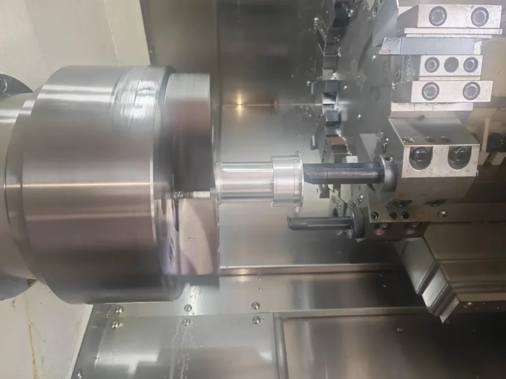
A rectangular housing commonly needs milling. A sleeve with concentric inner and outer diameters is a typical turning application. A turned part with side holes or flats may also require milling, either on a machine with suitable live tooling or in a separate setup.
Electrical discharge machining, or EDM, is another material-removal process used for electrically conductive workpieces. It uses electrical discharges rather than a rotating cutting edge. It can complement milling for certain difficult features, but it is not a solution for machining an ABS plastic component.
What the number of CNC axes means
A basic CNC lathe commonly controls X and Z tool movement while the workpiece rotates. A three-axis milling machine controls X, Y and Z linear movement. Four-axis milling adds one rotary axis, and five-axis milling adds two.
Rotary axes change the approach between the tool and part. They can make angled features accessible and reduce manual repositioning. However, a feature must still have physical clearance for the cutter, holder and machine movement.
Five-axis equipment can be used for positional machining or simultaneous motion. In 3+2 positional machining, the rotary axes orient the part or tool and remain fixed during a three-axis cut. In simultaneous five-axis machining, orientation can change during cutting. Haas describes both approaches in its five-axis machine overview.
More axes do not automatically mean a more accurate or less expensive part. A straightforward plate may be efficiently produced with three-axis milling. A part with several angled faces may benefit from five-axis access. The appropriate route depends on geometry, setup requirements and the drawing, rather than an assumption that every component needs the most complex machine.
Materials used in CNC machining
CNC machining can produce metal and plastic components directly from suitable stock without making a molding tool. Common metal families include aluminum, steel, stainless steel, brass, copper and titanium. Engineering plastics include ABS, POM or acetal, nylon, polycarbonate and PEEK.
These names identify material families, not interchangeable specifications. Alloy grade, temper, polymer grade, stock condition and any required certification should be established before ordering. A drawing calling for a particular material should not be changed simply because another material is available or easier to machine.
Metal machining needs a route suited to the alloy and its condition. Cutting behavior, tool wear, heat treatment and finishing requirements can affect both cost and dimensions. Plastic machining also needs attention to heat, support and clamping, especially around thin walls and long features.
In our CNC ABS work, the customer’s specified material remains the basis for production. We do not treat a switch to PC as a default upgrade or perform product strength testing to choose a replacement material. If a different material is proposed, the customer needs to approve it against the product’s requirements.
Material selection for service conditions belongs to the product design process. A machined prototype can help evaluate an assembly, but machining a named material does not by itself validate temperature resistance, fatigue life or suitability for a regulated application.
A real CNC machined ABS assembly
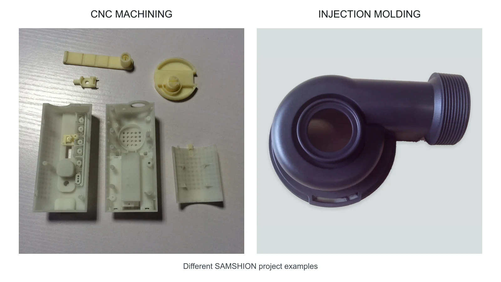
The components below are from a SAMSHION ABS project. They were CNC machined and assembled using screws. The photographs show the separate components and assembled form; they are not dimensional inspection records or evidence of strength testing.
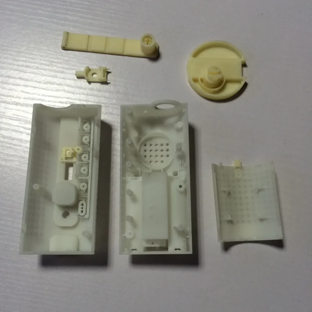
The separated view shows housing sections with internal features, openings and smaller components. This illustrates why manufacturing review needs to consider more than an exterior shape. Parts must be produced individually while retaining the geometry that allows them to come together.
For an assembly like this, relevant drawing information includes the interfaces between housing sections, fastener locations and the positions of components inside the enclosure. Where another supplied metal or plastic component must fit, its matching geometry or the actual mating part can be important to the agreed check.
Checking the assembled relationship
In our work on sets of mating prototype components, we normally trial-assemble the available parts after machining. The requirements come from the customer’s drawing or approved 3D data. The scope can include how parts seat together, whether holes align and how mating components fit. Documentation is supplied according to the customer’s requirements.
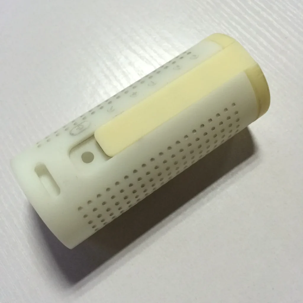
Trial assembly answers a different question from checking an isolated dimension. It can reveal interference or a seating problem in the available set, but it does not replace specified dimensional measurements. A single assembled set also does not establish interchangeability across a production batch.
This build-to-print scope does not include product development, strength testing or a general promise that the completed product performs its intended function. More details are covered in our prototype assembly checks guide.
CNC machining tolerances and surface finish
A machining tolerance defines an acceptable variation in a specified dimension or geometric relationship. Surface texture describes the condition of a surface. Cosmetic appearance adds another requirement: a surface can meet its dimensional tolerance and still have visible tool marks that are unacceptable for an exposed face.
There is no single tolerance that applies to every CNC part. Size, geometry, material, tool access, workholding and the measurement method all matter. A short, supported feature and a long, flexible wall do not present the same manufacturing problem.
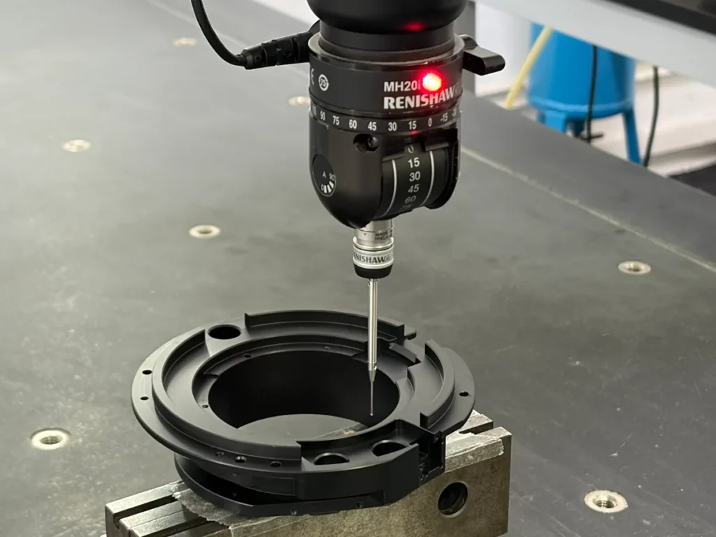
Identify the dimensions that control fit rather than applying an unnecessarily tight requirement everywhere. State datum references and geometric requirements where feature relationships matter. General tolerances need to be explicitly agreed; they should not be inferred from the number of decimal places in an unannotated CAD model.
Also state whether dimensions apply before or after treatment when this affects acceptance. Plating, paint or other treatments can change fit, and masking may be required. Our CNC surface finish guide discusses finishing separately so the drawing can distinguish texture, treatment and appearance.
For a quotation, supply the actual critical requirements instead of asking only for a supplier’s smallest advertised tolerance. The useful answer is whether your particular features can be made and verified as specified.
Design features that need early review
Internal corners and deep pockets
A rotating milling cutter leaves a radius where the pocket walls meet. A very small internal radius can require a smaller, less rigid tool and more cutting time. Specify a sharp corner only where its function requires it, and discuss an alternative process or permitted relief when necessary.
Deep, narrow pockets restrict both tool reach and chip clearance. Increasing depth without increasing access can require longer tools and more cautious cutting. A larger corner radius or wider opening may help, but the customer must approve any design change.
Thin walls and unsupported features
Thin walls can deflect during clamping and cutting. Wall height, unsupported span, material and the required accuracy matter as well as thickness. There is no universal minimum wall thickness that resolves all these factors.
The process may need temporary supporting material, staged cuts or suitable fixtures. If a proposed geometry cannot be held or cut reliably, the manufacturing discussion should happen before the order is released.
Threads and hidden features
Specify thread size and required engagement, and distinguish thread depth from total drilled depth. Blind holes may need additional space for tooling and chip clearance. Unnecessary thread depth can increase difficulty without helping the assembly.
Undercuts and hidden features require a feasible tool approach. For complex ABS prototypes without structural strength requirements, we sometimes propose splitting the design into separately machined pieces and bonding them, subject to customer approval. This is different from manufacturing a one-piece component and must not be done without agreement.
If the customer requires one-piece machining, we assess whether a suitable machining route, including five-axis access where relevant, is feasible. If it is not, we provide DFM suggestions for the customer to consider. Neither extra axes nor a larger machine can make every inaccessible internal feature machinable.
Advantages and limits of CNC machining
CNC is useful when the project needs parts made from specified machinable stock, controlled features or a small quantity without a dedicated molding tool. It can also support repeat production once the manufacturing route is established.
Its limits include physical tool access, material removal time and the need to hold the workpiece. A hollow shape that is easy to describe in CAD may be difficult to cut from solid stock. Large amounts of removed material can make a seemingly small component expensive.
Design revisions can often be handled by changing the model and machining program, but they are not automatically cost-free. Changes may also require different stock, fixtures, tools or inspection arrangements. Already machined parts may not be recoverable if material needs to be added.
Compared with 3D printing, machining removes rather than builds material. Compared with casting or molding, it does not normally require a dedicated mold to create the part’s primary shape. None of these distinctions makes one process universally better; geometry, material, quantity and acceptance requirements decide the appropriate route.
What affects the price of a CNC part
A CNC quote includes work beyond the time a cutter touches the part. Drawing review, programming and setup still have to be performed for a single prototype. Those preparation costs can be spread over more identical parts when quantities increase.
Geometry affects the machining time. Large material removal, deep cavities, small cutters and several setups can add more cost than the final part’s size suggests. Tight features can add finishing and measurement work, while coating and cosmetic requirements add operations after cutting.
For a useful price comparison, keep the revision, material, quantity, tolerances, finishing and documentation scope consistent. A lower price based on an omitted inspection report or a different finish is not an equivalent quotation.
For repeat batches, tooling, workholding and inspection planning deserve a separate review. Our CNC production machining guide covers that stage rather than treating a production order as a simple multiplication of the prototype price.
What to send for a CNC machining quote
Provide enough information to separate mandatory requirements from items that can be discussed during DFM review.
- A 3D model, preferably STEP or another agreed solid-model format, and a drawing where needed to communicate manufacturing requirements.
- Matching revision identifiers and units across the files.
- Material grade and condition, including any required material documentation.
- Order quantity and requested delivery date.
- Critical dimensions, geometric tolerances, threads and required mating relationships.
- Surface treatment, texture, cosmetic faces and any masking requirements.
- Inspection reports, trial assembly, supplied mating parts or other deliverables required with the order.
If only a model is available, identify any requirements that are not contained in it. If a dimension or acceptance criterion is unresolved, clarify it before manufacturing rather than assuming the supplier can determine the product’s functional needs.
Frequently asked questions
Can I order just one CNC machined part
Yes. CNC machining can be used for a single prototype without making a molding tool. Programming and setup still affect the price, so one part will not necessarily have the same unit cost as a larger batch.
Is a STEP file enough to manufacture my part
A STEP model can communicate the shape, but it may not communicate all acceptance requirements. Add the material, quantity and finish, and provide drawings or other agreed specifications for threads, critical tolerances and inspection needs. Resolve any conflict between the model and drawing before cutting.
Will five axis machining make any design possible
No. More approach angles can help, but the tool and holder still need clearance and the part still needs support. Fully enclosed features and some undercuts may require another process, an approved split construction or a design change.
Does a successful trial assembly prove product performance
No. It shows the observed fit of the parts checked within the agreed scope. It does not by itself prove strength, fatigue life, sealing, electrical function or other product performance, and it does not replace required dimensional inspection.
Do CNC machined parts always need a surface treatment
No. An as-machined surface may be acceptable when it meets the drawing and use requirements. Where treatment is needed, specify it before quotation so its effect on dimensions, appearance and delivery is included.
Discuss your drawing before production
SAMSHION provides custom CNC machining services for customer-specified metal and plastic parts. Send your model, drawing, material, quantity and finishing requirements for a manufacturability review and project-specific quotation. Include mating components or assembly requirements when they are part of the order, so the manufacturing and inspection scope is clear from the start.