
Production Mold Making for Repeat Injection Molding
SAMSHION designs and manufactures production injection molds for ongoing plastic-part supply. We develop tooling around your part design, specified resin and expected order volumes, then support mold trials and repeat injection molding at our facility.
- DFM and mold-design review before tool manufacture
- CNC machining, EDM, mold assembly and trials
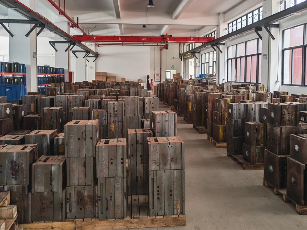
- Molds retained on site for repeat injection molding
- Recorded maintenance, repairs and tooling revisions
What Is Production Tooling?
Production tooling refers to the molds used to manufacture injection-molded parts across repeated production runs. A production mold combines cavity geometry, gating, cooling and ejection systems to form and release parts that meet the agreed dimensional, assembly and appearance requirements.
The first batch is only part of the planning picture. Expected total demand, individual batch sizes and the interval between orders help determine an appropriate tooling approach. Production tooling can support repeat orders placed as needed. It is not limited to continuous production at high volumes.
For designs still being validated, explore our rapid tooling services for prototype and bridge-production needs. For molded-part manufacturing, material options and ordering requirements, see our custom injection molding services.
Why Choose SAMSHION for Production Mold Making?
Tooling Planned Around Your Production Needs
Part geometry, specified resin, assembly requirements and expected order volumes guide our tooling recommendations. These factors are reviewed before mold manufacture to align the tooling approach with your product requirements and production plans.
Coordinated Mold Manufacturing and Trials
CNC machining, EDM, fitting, mold assembly and trial molding are coordinated throughout the tooling project. Findings from T1 samples guide the review of tooling and molding conditions, with agreed corrections recorded for follow-up.
Molds Retained for Repeat Orders
Production molds remain at SAMSHION for subsequent injection molding orders. Mold identification, storage and maintenance records support preparation for future runs. Repairs and tooling changes are reviewed with you to confirm the scope before work proceeds.
Inspection Based on Agreed Requirements
Inspection is planned around the approved drawing and agreed requirements for critical dimensions, assembly fit, appearance and color. Required reports and acceptance criteria are confirmed for each project, providing a clear reference for sample review and repeat production.
Production Mold Projects and Repeat Supply
These parts were produced using molds manufactured by SAMSHION. Each example highlights the material, part features and project-specific requirements for assembly, appearance or functional fit.
ABS+PC Equipment Housing
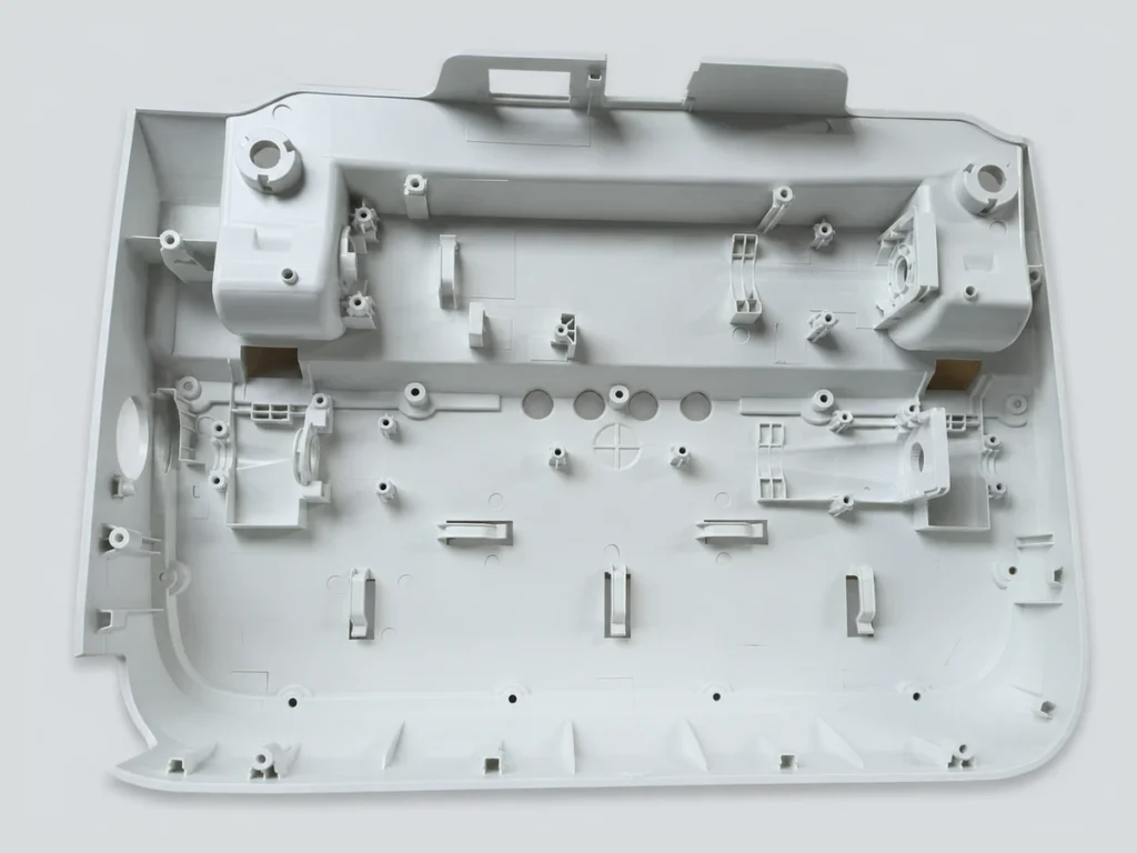
This injection-molded ABS+PC equipment housing incorporates reinforcing ribs, mounting features and snap-fit details. Key requirements include mounting-hole positions, snap-fit engagement, flatness, appearance and color. Warpage control is a central consideration for the housing’s fit and assembly.
PP Automotive Threaded Components
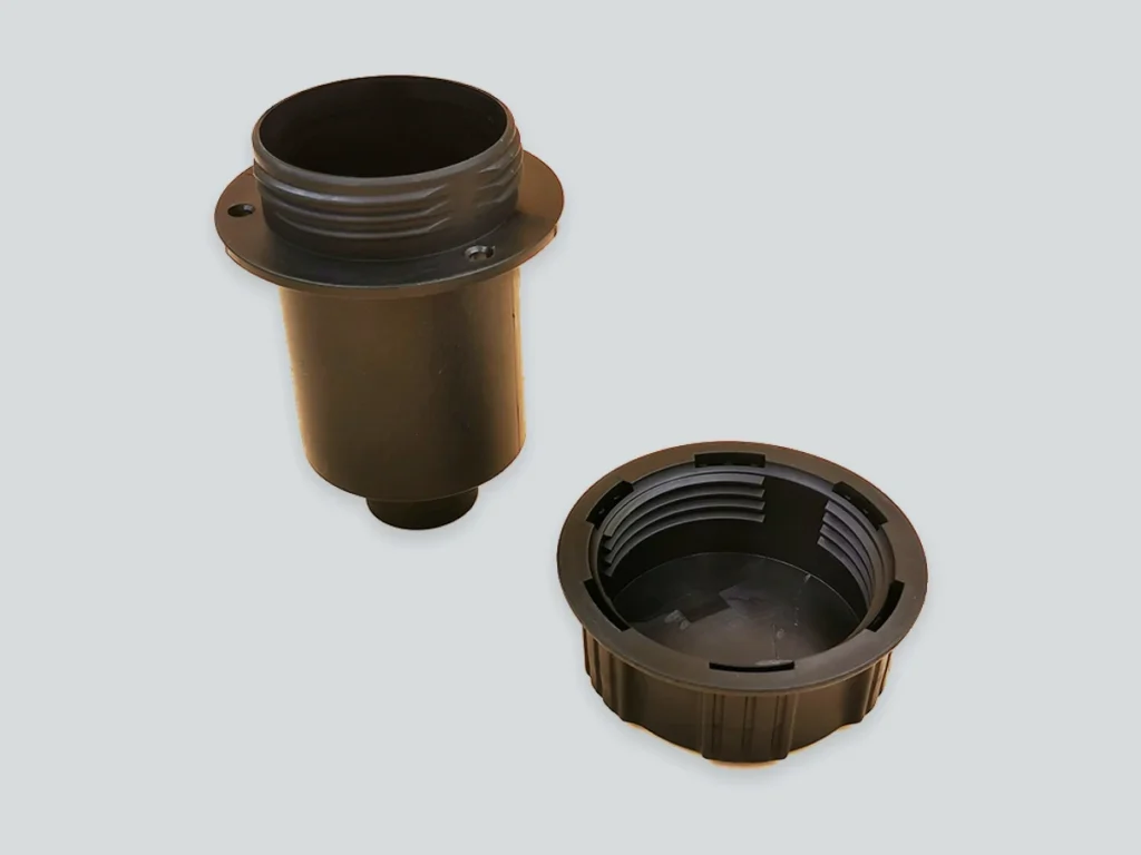
These mating PP automotive components feature internal and external threads formed directly by injection molding. Project requirements include thread fit, smooth screw engagement, assembly dimensions and appearance. The assembled components also have sealing requirements.
ABS Water Pump Component
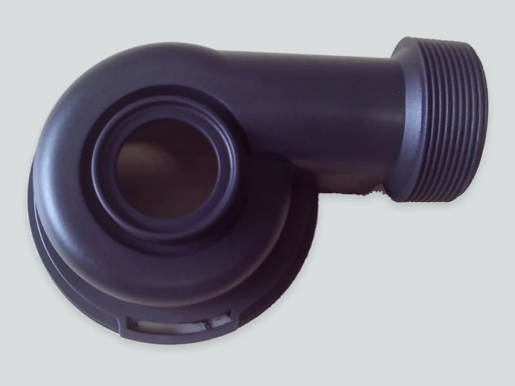
This ABS water pump component is injection molded as a single piece, including the external thread. The threaded connection is a key functional feature, with thread engagement and fit to the mating component central to its intended use.
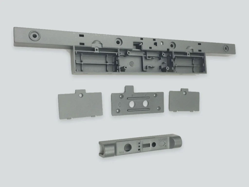
ABS+PC Combination Lock Components
These mating ABS+PC components are manufactured for one combination lock product using shared tooling. The parts are painted gray after injection molding and supplied as complete sets. Key requirements include assembly fit, hole positions, snap-fit engagement, long-part flatness, and consistent appearance and color.
Production Requirements for Mold Design
A production mold should be planned around more than the 3D model. Part requirements, material specifications, order quantities and acceptance criteria provide the basis for tooling decisions. Items that remain open should be identified during the project review.
Part Drawings and Assembly Requirements
Provide the current 3D model and available 2D drawings, identifying critical dimensions and mating features. Highlight requirements for mounting holes, snap fits, threads, sealing surfaces and flatness, along with any assembly or functional checks needed for part approval.
Resin, Color and Surface Requirements
Specify the resin manufacturer and grade where defined, together with the required color reference and surface finish. Identify visible surfaces and any material restrictions. Proposed material alternatives or changes to appearance requirements should be reviewed before tooling decisions are finalized.
Order Quantities and Production Schedule
Share the expected first-order quantity, typical repeat-order quantities and likely ordering frequency. Estimated annual or total demand helps guide tooling and capacity planning. For order-based supply, identify any seasonal peaks or delivery schedules that may affect production requirements.
Inspection and Approval Requirements
Define how samples and production parts will be accepted, including dimensional checks, assembly fit, appearance and any required functional tests. Request inspection reports, material documentation or customer-specific approval formats before quotation so the required scope can be included in project planning.
Injection Mold Types and Cavity Strategies
The mold types below cover cavity layouts and specialized molding or demolding features. These categories are not mutually exclusive; for example, a multi-cavity mold may also use an unscrewing mechanism.
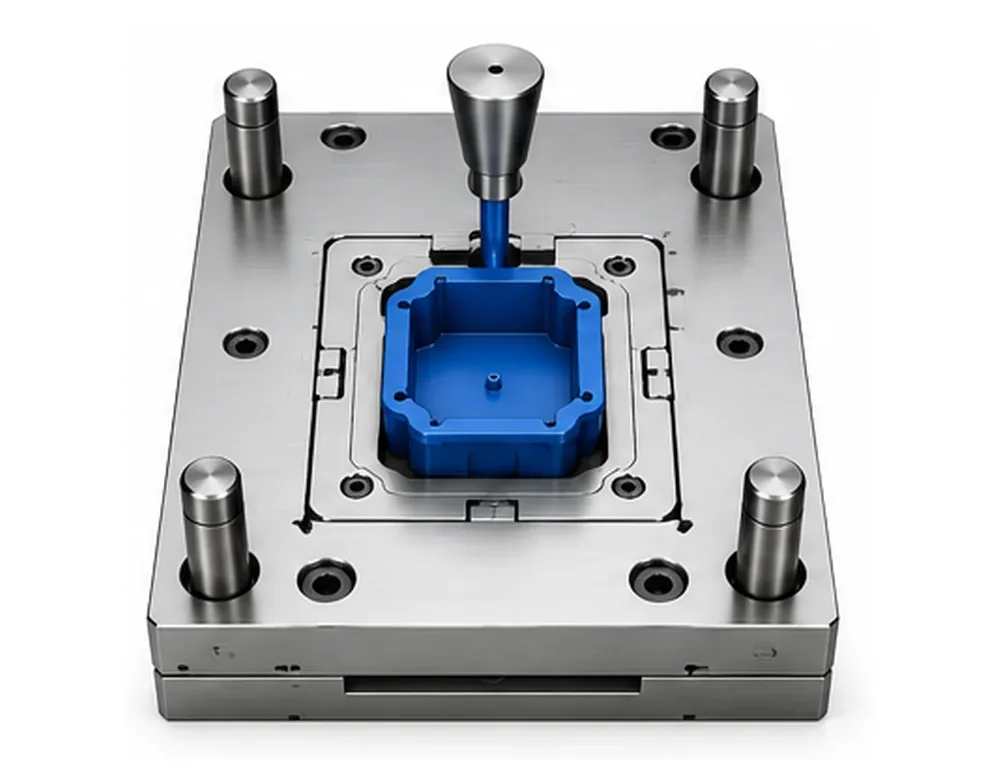
Single-Cavity Production Molds
A single-cavity mold produces one part per cycle. It can be a practical production choice for larger components, complex geometries or repeat-order quantities that one cavity can supply at the required production rate.
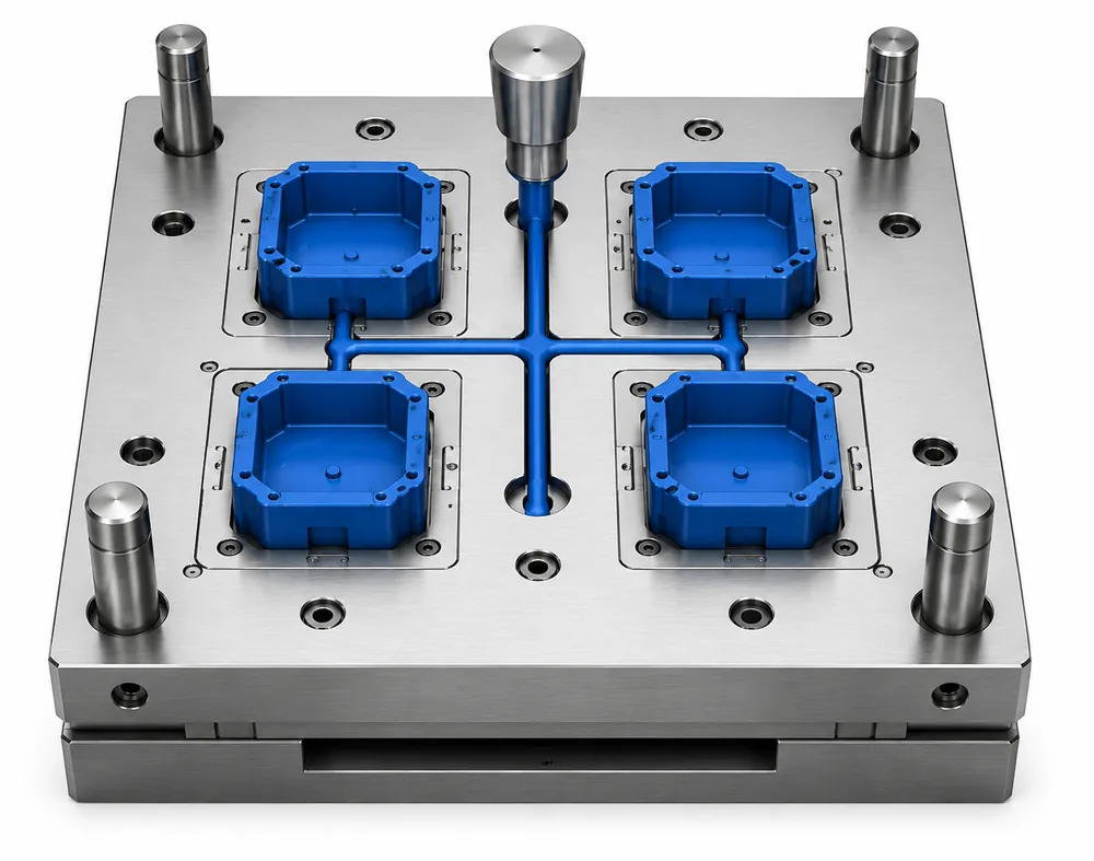
Multi-Cavity Molds
A multi-cavity mold produces several identical parts per cycle. Its design focuses on consistent filling, cooling and part quality across cavities. Individual cavity identification supports traceability when comparing dimensions, investigating variation or planning maintenance.
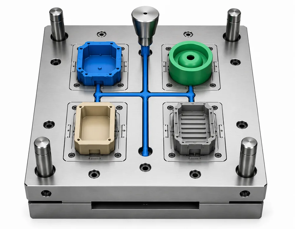
Family Molds
A family mold produces different components in the same cycle using a common material. The main considerations are compatible filling and cooling behavior, together with a cavity mix that matches the required production ratio of the different components.
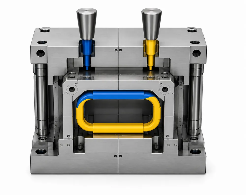
Two-Shot and Multi-Component Molds
Two-shot and multi-component molds form parts from different materials or colors in a controlled sequence. Material compatibility, the interface between components and the method used to transfer or index the part between molding stages are key design considerations.
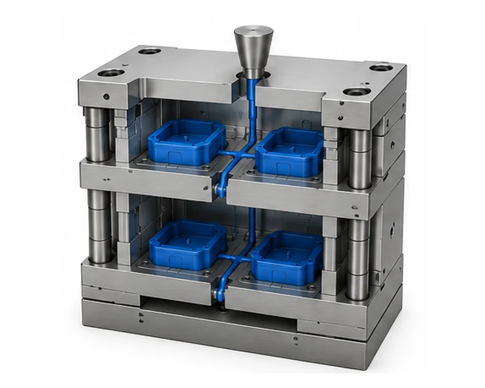
Stack Molds
Stack molds place cavities on multiple parting levels to increase output. Design must coordinate mold opening, melt delivery and ejection across those levels, while accounting for machine opening space, injection capacity and mold support.
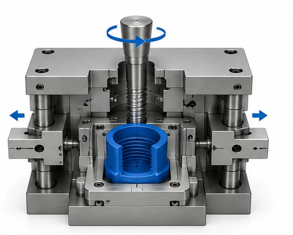
Unscrewing and Side-Action Molds
Unscrewing mechanisms release molded threads through controlled rotation. Slides and lifters clear undercuts or side features that prevent straight-pull release. These mechanisms solve different demolding problems and may be used separately or together within a mold.
Production Mold Steel and Component Selection
Mold bases, cores, cavities and moving components do not necessarily use the same steel. Materials and components are selected for their roles in the tool, including structural support, surface finish, local wear and access for replacement.
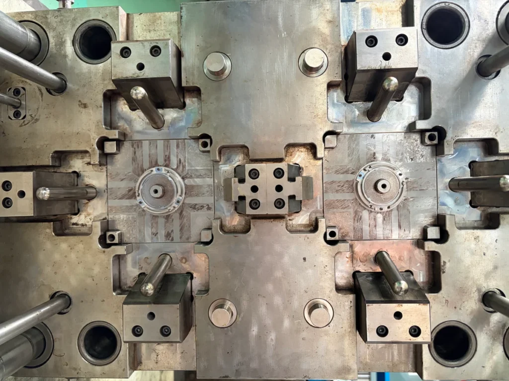
Prehardened Mold Steel
Prehardened steel is supplied at a specified hardness and can often be machined without a separate hardening stage. It can suit mold bases and cavity blocks where the supplied condition provides the required balance of machinability, strength and surface finish.
Hardened Tool Steel
Suitable tool steels can be hardened to a specified working condition where greater resistance to wear or deformation is needed. Heat treatment and subsequent finishing must account for dimensional changes while maintaining the toughness required for the component.
Corrosion Resistance and Polishability
Corrosion-resistant grades help address corrosion risks associated with the resin and operating environment. Steel cleanliness and polishability also matter for demanding cosmetic surfaces. These requirements can apply to either prehardened or hardened steels, depending on the selected grade.
Standard Components and Replaceable Inserts
Standard guide, ejection and locating components can simplify sourcing and replacement. Replaceable inserts allow selected wear areas or local features to be serviced without replacing an entire cavity block. Component fit and replacement access must be considered during mold design.
Mold Surface Finish and Appearance Requirements
SAMSHION coordinates mold surface finishing through specialist external suppliers. Common SPI finishes and customer-specified textures are reviewed and arranged as part of the tooling project.
SPI Surface Finish Grades
Specify the required SPI finish grade and identify the relevant mold surfaces on the drawing. Mark any areas that require a different finish so the processing boundaries are clear.
Specified Mold Textures
Texture codes or reference samples define the intended pattern. The selected texture is reviewed for suitability with the mold before processing, including any specified transitions between textured and untextured areas.
Customer Appearance Approval
Final appearance should be reviewed on molded samples against the agreed visual criteria. Customer approval is required, with any additional appearance requirements defined before surface finishing begins.
Injection Mold Design and DFM Review
Our design for manufacturability (DFM) review identifies design risks before mold manufacture, covering part release, filling, cooling, structural support and maintenance access.
Mold Opening and Parting Lines
Review the opening direction, core and cavity split, parting lines and shutoffs. Identify undercuts and the mold actions needed to release the part while maintaining the required mating surfaces.
Draft, Texture and Ejection
Check draft, textured surfaces and ejector locations together. The release strategy should limit dragging, sticking and excessive ejection force, with part handling considered where marking or distortion is a concern.
Wall Thickness and Core Support
Review wall transitions, ribs and bosses for molding risks. Check slender cores and unsupported steel for adequate support and stiffness under molding pressure.
Gates, Runners and Venting
Assess gate locations and runner layout for balanced filling. Plan venting at likely air traps and the end of fill, considering gate marks and the cosmetic areas that must be protected.
Cooling Circuit Layout
Review cooling channel layout around cavities, cores and local thick sections. Circuit routing must account for inserts and moving components, with attention to temperature balance and access to cooling connections.
Maintenance and Safe Access
Review access to wear components, fasteners and service connections. Mold lifting points, handling arrangements and maintenance clearances should be considered during design, with project-specific safety requirements defined before manufacture.
Mold Flow Analysis for Production Tooling
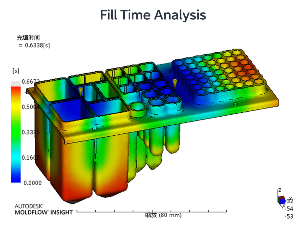
After order confirmation, SAMSHION carries out mold flow analysis to support mold design decisions. The analysis helps review the proposed molding approach and identify potential concerns that require further engineering attention.
Analysis results are typically shared with the customer to support discussion of the mold design. Findings are considered alongside the part geometry, specified material and relevant molding conditions when evaluating potential design adjustments.
Simulation supports engineering decisions but does not replace mold trials or part inspection. Trial results and measured parts are used to check actual molding behavior and assess whether further adjustments are needed.
Hot Runner or Cold Runner?
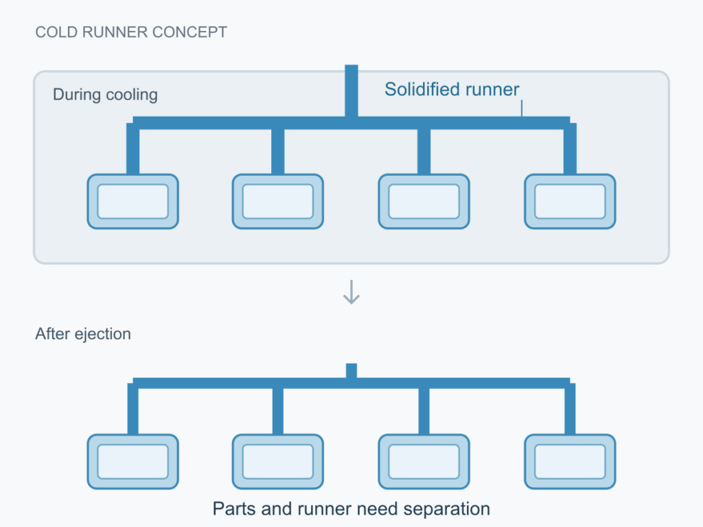
Cold Runner Systems
In a cold runner mold, resin in the runner solidifies during each cycle and is ejected for separation from the parts. The system generally requires simpler tooling and a lower initial investment, but runner material, separation and handling add to production cost. Reuse of runner material must follow the agreed material and quality requirements.
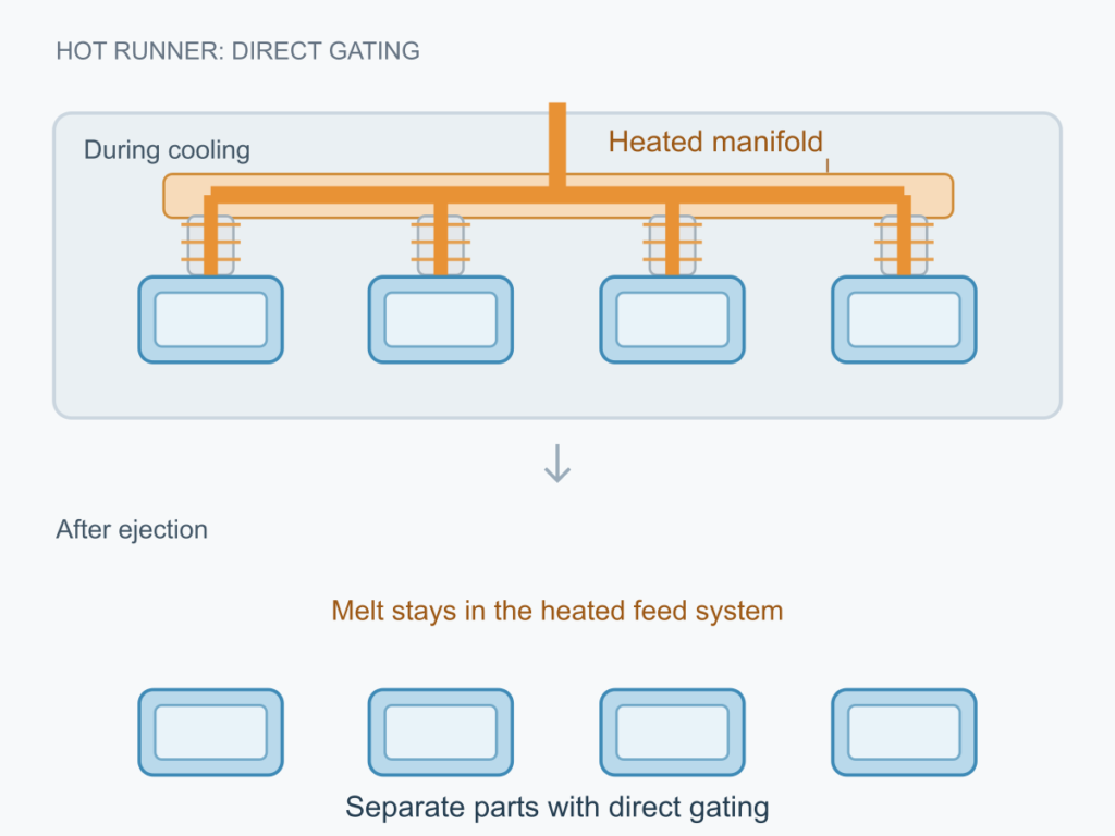
Hot Runner Systems
A hot runner system uses heated components to keep resin molten within the feed system between cycles. It can reduce solidified runner material and support direct gating, but adds temperature controls, initial cost and maintenance requirements. Material sensitivity, melt residence time and color changes need consideration. Some designs combine hot runners with short cold runners.
Choosing the Right Runner System
Selection should consider resin compatibility, runner weight, gate requirements, expected total demand, batch size and changeover frequency. For repeat orders placed as needed, startup and purging losses should be considered alongside steady production costs. The preferred system balances part requirements, tooling investment, material use and maintenance.
How SAMSHION Manufactures Production Molds
Once the mold design is approved for manufacture, work progresses through machining preparation, component manufacture, inspection and assembly. Each stage prepares the tool for fitting and trial molding.
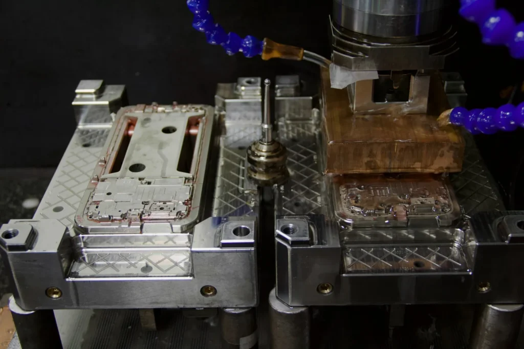
Manufacturing Drawings and Preparation
Released mold drawings define the components, dimensions and fits required for manufacture. Machining plans and electrode requirements are prepared around the selected materials and mold structure.
CNC and EDM Machining
CNC machining shapes mold plates, cores, cavities and inserts. EDM is used where appropriate for details that are difficult to produce with cutting tools. The machining sequence follows the component geometry and material condition.
Mold Component Inspection
Machined components are checked against their drawings, with attention to dimensions, locating features and mating surfaces. These checks support correct fitting and alignment during assembly.
Fitting and Mold Assembly
Mold plates, inserts and moving components are fitted and assembled. Checks cover alignment, shutoff contact, moving clearances and ejection movement before the mold proceeds to trial molding.
T1, T2 and Mold Sample Approval
T1 and T2 identify trial stages, not automatic approval levels. The number of trials depends on the findings, required corrections and agreed acceptance criteria.
Initial Mold Trial (T1)
The initial trial checks mold operation, filling and part release. Samples are reviewed against the agreed drawing, material and key part requirements, with attention to dimensions, appearance and assembly.
Review and Corrective Actions
Trial findings help identify whether an issue relates to the mold, part design, material or molding conditions. Proposed corrections should address the identified cause and define which features need to be checked again.
Follow-Up Trials
Where corrections are needed, T2 or later trials assess their effectiveness. Review should include both the original issue and other features that may be affected by the change, such as neighboring dimensions, appearance or part release.
Customer Sample Approval
Samples are submitted for customer review against the agreed dimensional, appearance and functional requirements. Any remaining issues and the scope of approval should be clearly recorded before the next production stage.
For a detailed review checklist, see our T1 injection molding sample approval guide.
Mold Storage, Maintenance and Repeat Production
SAMSHION retains production molds at our facility for repeat injection molding orders. Mold identification, maintenance records and checks before production resumes support continued use between orders.
Mold Identification and Storage
Each mold has a unique identification number linked to its project. This helps locate the correct tool when a repeat order is scheduled and distinguish it from other molds in storage.
Maintenance and Controlled Repairs
Mold care includes cleaning, corrosion protection and lubrication as required. Maintenance, repairs and modifications are recorded. The scope of any repair or modification is confirmed with the customer before work proceeds.
Checks Before Repeat Production
Before a repeat run, we check the applicable drawing revision, material and color requirements. Initial parts are inspected against the agreed criteria, with reference samples used for comparison where applicable.
Tooling Cost and Production Planning
Evaluate tooling investment alongside the expected cost and timing of part supply. Planning should reflect realistic order quantities, possible design changes and the requirements for repeat production.
Tooling Investment and Part Cost
Compare the mold investment separately from the cost of molded parts. Part pricing should account for material use, cycle time, order quantity and any agreed finishing, inspection or packaging. A lower mold price does not necessarily give the lowest overall project cost.
Batch Size and Expected Demand
Evaluate the first order alongside likely repeat orders. Compare tooling options across realistic quantity scenarios rather than relying on an assumed future volume. The value of a larger initial investment depends on whether the expected demand is actually realized.
Design Changes and Cost Impact
Changes after tooling begins can affect both mold cost and the delivery schedule. Before a modification proceeds, its scope should be reviewed together with any machining, replacement components, new samples or inspection needed.
Repeat Order Scheduling
For repeat orders, production planning should consider material availability, mold readiness and machine capacity. Required quantities and delivery dates should be discussed when arranging the next run. Retaining a mold supports repeat supply, but each order still requires production scheduling.
Frequently Asked Questions
What Is the Difference Between Rapid Tooling and Production Tooling?
Rapid tooling commonly supports design validation, pilot batches and bridge supply. Production tooling is planned around repeat manufacturing, maintenance and expected demand. The distinction is not simply aluminum versus steel; the appropriate tool construction depends on the part, material and production requirements.
How Long Does a Production Mold Take to Build?
Lead time depends on mold complexity, material availability, machining, surface finishing and the required trials. The project schedule should distinguish the target date for initial samples from customer approval and production release. Required corrections can affect the overall timeline.
How Many Cycles Will a Production Mold Last?
Mold life depends on tool construction, resin, operating conditions, wear and maintenance. A single cycle count cannot describe every mold. Any target service life should be agreed together with the intended material, maintenance requirements and part acceptance criteria.
Can Production Molds Support Orders Placed as Needed?
Yes. SAMSHION retains production molds for repeat injection molding orders, including orders placed at irregular intervals. Each run is scheduled according to the required quantity, material readiness, mold condition and available production capacity.
Can One Mold Produce Different Parts?
Yes. A family mold can produce different components in the same cycle using a common material. Suitability depends on compatible filling and cooling requirements, together with a cavity arrangement that matches the quantities needed for each component.
What Happens After T1?
Initial samples and trial findings are reviewed against the agreed requirements. Where issues remain, corrective actions are defined and further trials are arranged as needed. T1 or T2 does not automatically mean approval; the next stage depends on the review findings and customer acceptance.
Where Is the Mold Stored Between Orders?
Production molds remain at SAMSHION for repeat injection molding. Each mold is identified by its project, with maintenance and modification records supporting continued use. Applicable drawing, material and color requirements are checked before repeat production.
What Documentation Can Be Supplied?
The documentation package is agreed by project. Requirements such as dimensional reports, material certificates or customer-specific approval formats should be identified before quotation. We then confirm what can be provided, including the scope, timing and any associated cost.
Start Your Production Mold Project
Upload your CAD model and drawings, and share the material, first-order quantity and expected repeat demand. SAMSHION will review your requirements and prepare a project-specific quotation for production tooling and injection-molded part supply.