
Rapid Tooling Services for Prototype and Low-Volume Injection Molding
Move from design validation to molded parts in the specified thermoplastic. SAMSHION designs and manufactures aluminum, prehardened steel and hybrid rapid tooling for prototype molding, pilot builds, bridge production and repeat low-volume orders.
- T1 samples from 15 business days after mold design approval
- In-house mold design, CNC machining, EDM, fitting and trial molding
- Customer-owned tooling after tooling fees are paid in full
- CMM reports and material documentation available according to the agreed project scope
Rapid Tooling Capabilities at a Glance
Review the tooling routes, development stages and validation support available for prototype and low-volume injection molding programs.
Tooling Matched to the Program
Aluminum, prehardened steel and hybrid construction are evaluated against the resin, part geometry, finish, expected demand, wear risk and revision needs.
Prototype, Pilot and Bridge Support
Rapid tooling can support injection-molded validation parts, pre-production builds, bridge supply and compatible repeat low-volume orders.
Specified Thermoplastic Grades
Trial parts can be molded in the specified resin grade and color when material behavior, assembly or molding effects must be evaluated.
Tooling DFM Before Release
Opening direction, draft, undercuts, gates, venting, ejection, cooling and likely revision areas are reviewed before tool manufacture.
T1 Review Before Production
Initial molded parts are reviewed against the agreed dimensional, appearance and functional requirements before production release.
Traceable Revision Control
T1 feedback is converted into defined tooling, process, drawing or inspection actions. Affected requirements are rechecked after relevant changes.
Rapid Tooling Built Around Your Validation Objective
Rapid tooling is not defined by one mold material, cavity count or standard tool-life target. A tool intended for assembly validation may require a different construction from one used for pilot orders or bridge production. The design should reflect what the molded parts are expected to prove.
SAMSHION begins by defining the evidence required from T1 and the expected path after sample approval. We then establish a practical tool concept, identify which production assumptions must be represented and document any known limitations before manufacturing begins.
For projects that still require process selection, explore our rapid prototyping services and low-volume manufacturing solutions.
What Is Rapid Tooling?
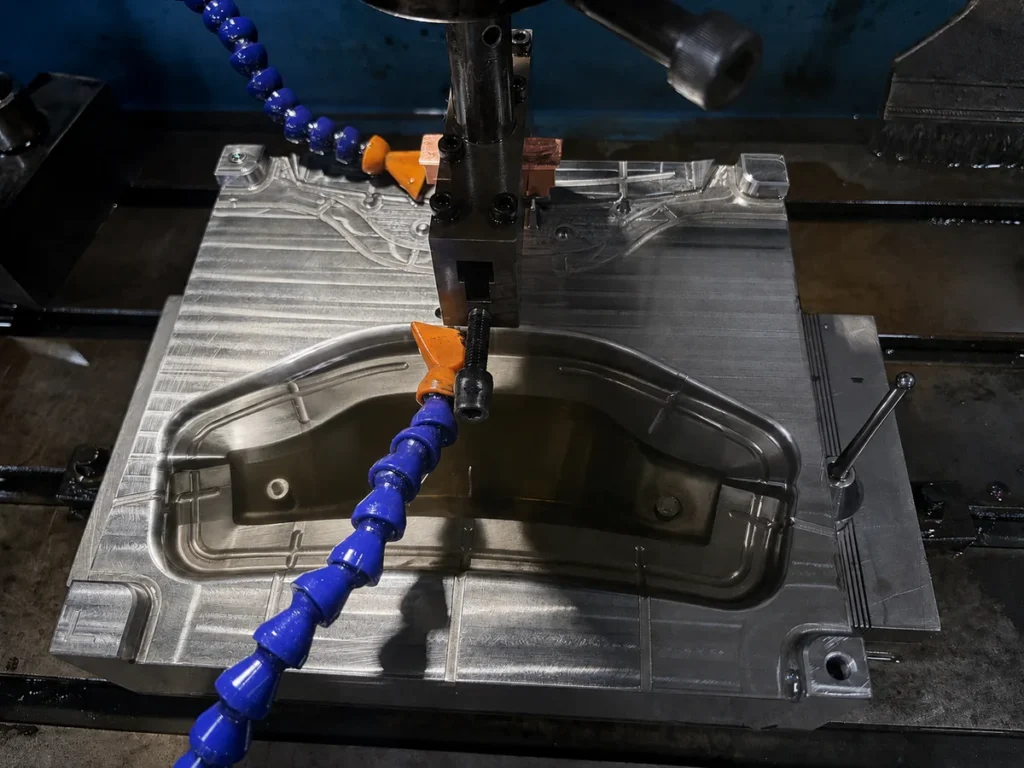
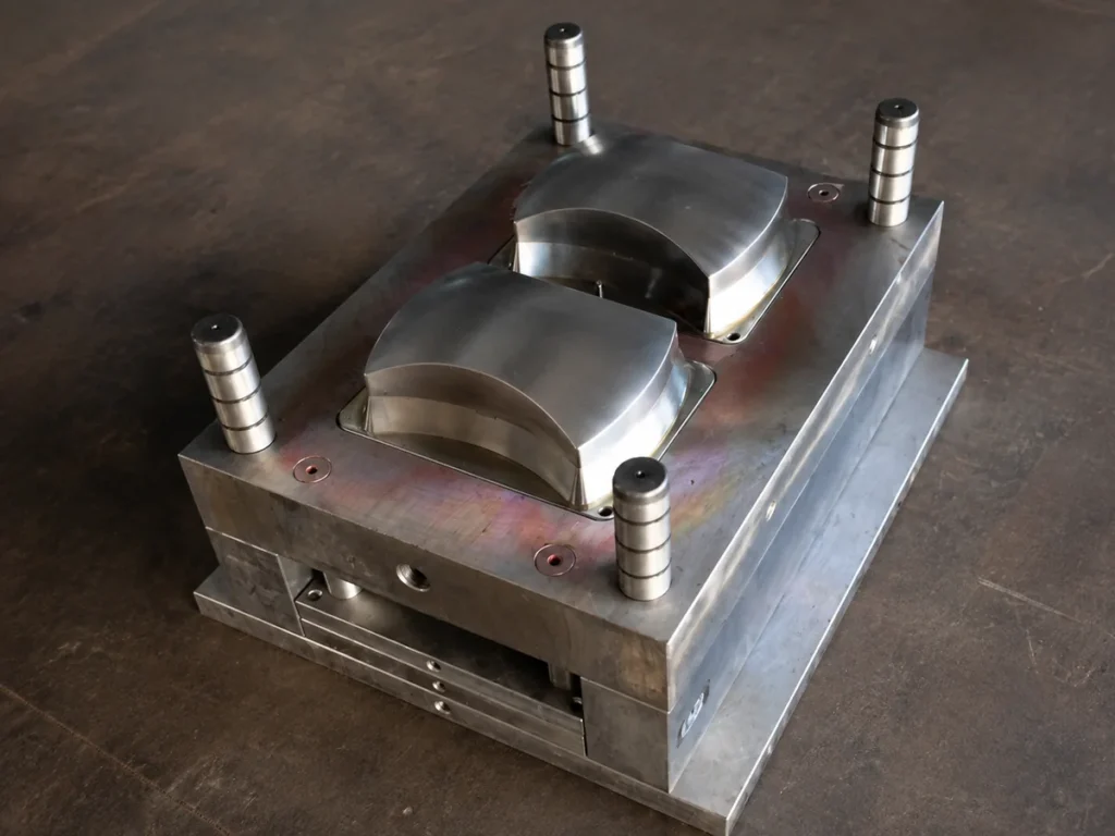
Rapid tooling is the manufacture of an injection mold designed to reduce the time and initial commitment required to obtain molded parts. Depending on the program objective, it may use aluminum, prehardened steel, standard mold bases, replaceable inserts or a hybrid construction.
The terms prototype tooling, pilot tooling, bridge tooling and low-volume tooling describe different program roles. They may use similar mold construction methods, but they should not be treated as interchangeable.
Prototype Tooling
Prototype tooling produces injection-molded samples in the specified thermoplastic. These parts can help evaluate material behavior, gate and ejector marks, shrinkage, assembly and other mold-driven effects.
Pilot Tooling
Pilot tooling supports engineering or pre-production builds used to confirm assembly, inspection, packaging and manufacturing procedures before a wider production release.
Bridge Tooling
Bridge tooling provides temporary production capacity for early orders or demand ramp-up while the final production mold is being manufactured, qualified or expanded.
Low-Volume Tooling
Low-volume tooling supports repeat production when expected demand does not justify a more complex high-volume mold. It may be the final manufacturing route rather than a temporary tool.
When comparing this approach with longer-life tooling, review our rapid tooling versus production tooling guide for differences in cavity strategy, maintenance, validation and lifecycle cost.
Why Choose Samshion For Rapid Tooling?
SAMSHION coordinates steel and aluminum rapid molds for prototype injection molding, pilot builds and low-volume production through one engineering route.
One Engineering Route from Mold Design to Molded Parts
Our in-house team coordinates mold design, CNC machining, EDM, fitting, injection molding trials and inspection against the same approved files. This reduces handoff risk and makes T1 findings easier to trace to part design, tooling or molding conditions. Learn how rapid tooling connects with our custom injection molding services.
Select the Process Before Committing to Tooling
Rapid tooling is compared with CNC machining, 3D printing and vacuum casting according to material, geometry, quantity and the evidence your program needs. This helps avoid mold investment while the design is still better served by another prototyping route.
T1 Sampling Linked to Measurable Corrections
After the first mold trial, samples are reviewed against the agreed dimensional, appearance, assembly and functional requirements. Findings are translated into defined tool, process, drawing or inspection actions before the next sample or production release.
Customer-Owned Tooling and Project-Specific Evidence
After full tooling payment, the rapid mold belongs to the customer. CMM reports, material documentation, sample records and other quality evidence are supplied according to the agreed project scope, so repeat orders follow a defined revision and acceptance basis.
Rapid Tooling Part Examples
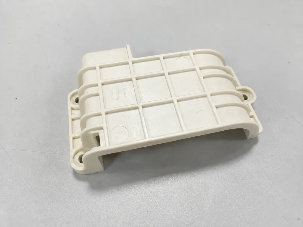
Explore a selection of components manufactured by SAMSHION using rapid tooling for low-volume injection molding, including ribbed parts, cylindrical components and small POM parts.
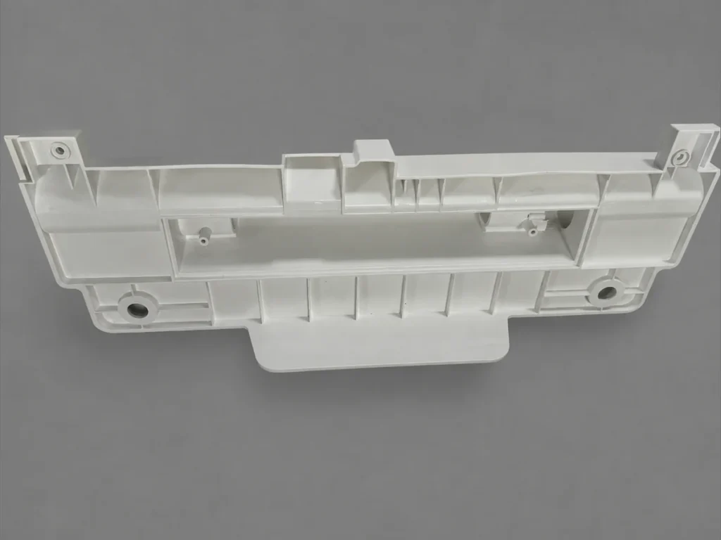
ABS+PC Ribbed Component for Low-Volume Production
SAMSHION produced this ABS+PC component using rapid tooling for low-volume injection molding. The elongated part features ribs, bosses and holes, bringing several molded features together in a single component.
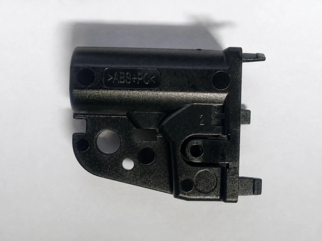
Black ABS+PC Component with Ribs and Openings
SAMSHION manufactured this black ABS+PC part using rapid tooling for low-volume production. The component features reinforcing ribs, circular openings and molded edge details.
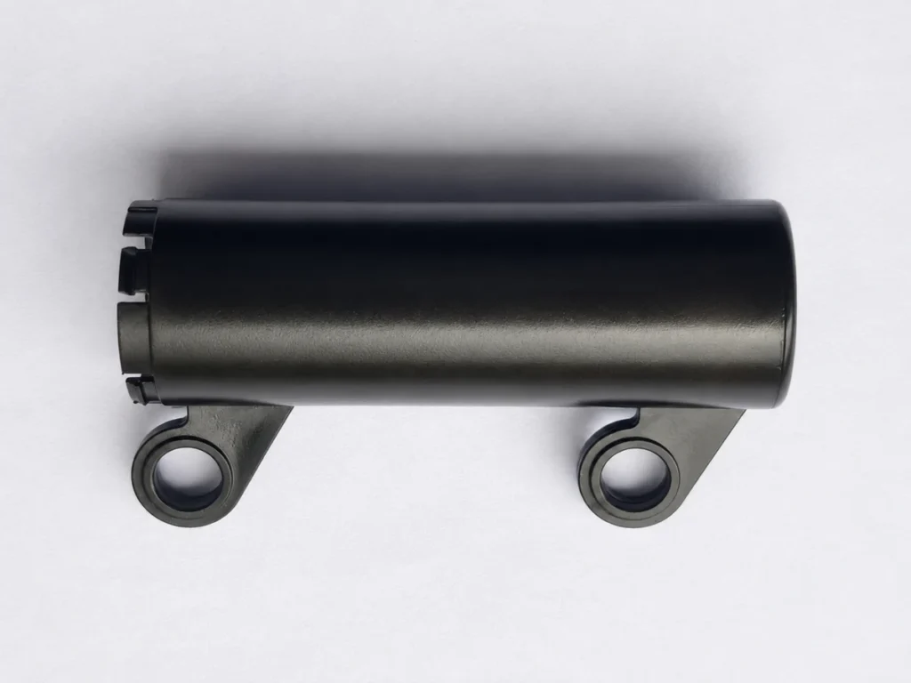
Black PC+ABS Cylindrical Component
SAMSHION produced this black PC+ABS component using rapid tooling for low-volume injection molding. The part features a cylindrical body and two side tabs with circular openings.
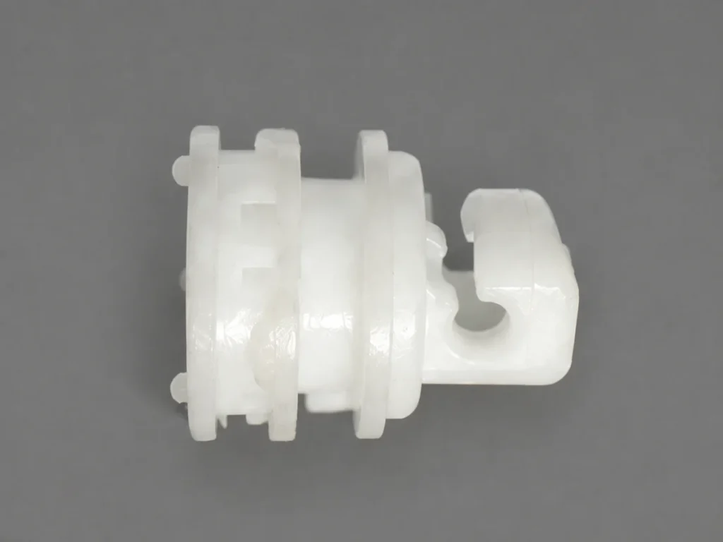
Small POM Injection-Molded Component
SAMSHION manufactured this small POM component using rapid tooling for low-volume production. The white part features circular flanges and an open-sided detail.
When Rapid Tooling Is the Right Manufacturing Route
Rapid tooling is appropriate when a program needs production-resin evidence or controlled molded quantities before investment in a long-life production mold is justified.
Validate Parts in the Intended Resin
Printed and machined prototypes are valuable, but they do not always reproduce the behavior of an injection-molded thermoplastic. A rapid mold can produce samples in the specified resin grade and color, allowing the team to evaluate fit, stiffness, snap engagement, sealing, chemical resistance, appearance and assembly under more representative conditions.
Material behavior still depends on drying, molding parameters, gate location, flow orientation and test conditions. Molded samples should therefore be treated as evidence from a defined process, not as proof that every future production condition will produce the same result.
Confirm Moldability Before Production Tooling
Rapid tooling can reveal filling, venting, sink, warpage, ejection and cosmetic risks while design and tooling changes are still manageable. These findings can guide the final mold concept, provided that differences in material, gate design, cooling and cavity layout are considered.
When demand and product requirements are sufficiently stable, the program can transition to a longer-life production mold.
Supply Pilot Builds and Market-Entry Quantities
Pilot injection molding supports assembly trials, field evaluations, packaging checks and initial customer demand using the specified thermoplastic. Controlled quantities allow the product team to gather practical feedback before committing to larger inventory or higher-capacity tooling.
For programs requiring coordinated pilot batches and repeat supply, review our low-volume manufacturing services.
Bridge a Production Capacity Gap
Bridge tooling can supply molded parts while a multi-cavity production mold, automated molding cell or additional manufacturing capacity is being completed. It can also support an early market launch or temporary increase in demand.
Dimensional, cosmetic and functional differences between the bridge mold and the future production system should be identified before approval so that parts from each route can be evaluated correctly.
Support Products with Stable but Limited Demand
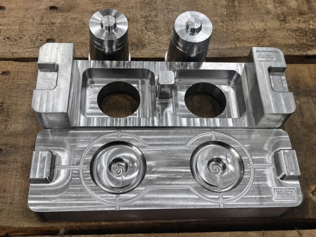
Industrial equipment, specialist electronics, replacement components and configurable products may have stable demand without requiring a high-volume mold. A maintainable aluminum or prehardened steel rapid mold can provide a practical long-term manufacturing route when resin, geometry, finish and expected quantities are compatible with its construction.
Learn more about manufacturing support for industrial equipment parts.
Rapid Tooling Materials and Mold Construction
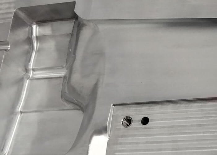
Rapid tooling is not defined by one mold material. SAMSHION selects aluminum, prehardened steel, hardened inserts or modular construction according to the resin, part geometry, surface requirements, expected demand, wear risk and likely design changes.
Aluminum Rapid Tooling
Aluminum rapid tooling is suitable for prototype injection molding and selected low-volume programs using compatible, relatively non-abrasive thermoplastics. Its machinability and heat transfer can shorten toolmaking and support efficient molding. Confirm the alloy, finish, wear areas and expected demand before selection.
Prehardened Steel Rapid Tooling
Prehardened steel rapid tooling is chosen when greater wear resistance, polishability, repairability or repeat output is needed. It supports more demanding gates, shutoffs and loaded features. Confirm the steel grade, hardness, finish, corrosion risk and maintenance requirements.
Hybrid Tooling with Hardened Inserts
Hybrid rapid tooling uses hardened or replaceable inserts at gates, cores, slides, shutoffs or textured areas while keeping the remaining tool construction practical. Confirm the insert material, fit, cooling, replacement access and likely correction areas.
Standard Mold Bases and Modular Inserts
Standard mold bases and modular cavity inserts can support related parts, design variants or repeat programs that share a common tooling architecture. Confirm the insert envelope, gating, venting, cooling, ejection, part identification and changeover plan.
Injection-Molded Materials for Rapid Tooling
SAMSHION evaluates ABS, PC, PC/ABS, PP, PE, POM, PA, TPE and TPU for prototype and low-volume injection molding. Selected reinforced and high-performance resins can also be reviewed for compatibility with the proposed mold and processing conditions.
Material selection starts with the part’s function. ABS and PC/ABS are common candidates for housings and covers, while POM and PA may suit gears, guides and mechanical components. PP and PE offer options for containers and selected flexible features. TPE and TPU can be considered for grips, seals and other compliant parts. Suitability depends on the specific grade and application.
For quotation, provide the resin manufacturer and grade if already selected, together with color, reinforcement, operating conditions and required material documentation. SAMSHION reviews shrinkage, drying, processing temperature and tooling wear before confirming the molding route.
Explore our injection molding materials guide for additional information about thermoplastics, reinforced resins and material specifications.
T1 Mold Trials and Sample Approval
T1 is the initial mold trial used to evaluate tooling performance and injection-molded samples. SAMSHION documents the findings, coordinates corrections and submits samples for review. Production release follows the agreed approval process.
Record the T1 Trial Conditions
The trial record identifies the resin grade, color, drying conditions, molding machine and key process settings. Relevant temperatures, injection, packing and cooling conditions provide a reference for interpreting sample results and comparing subsequent trials.
Inspect the Molded Samples
T1 samples are checked for critical dimensions, filling, flash, sink marks, warpage, gate marks and visible surface requirements. Assembly and functional checks follow the agreed project scope. Dimensional reports, including CMM results where appropriate, support the sample review.
Resolve Findings and Recheck Samples
Trial findings are reviewed to determine whether they require process adjustment, mold correction or a proposed part-design change. Agreed actions are recorded, and affected features are checked on revised samples. Changes to the customer’s part design require approval before implementation.
Document Approval Before Production
Sample identification, part and tool revisions, inspection results and any agreed deviations establish the approval record. Outstanding issues and required follow-up checks are documented before release for the agreed pilot or low-volume production batch.
Learn more about our quality assurance and inspection capabilities.
Rapid Tooling Design and DFM Review
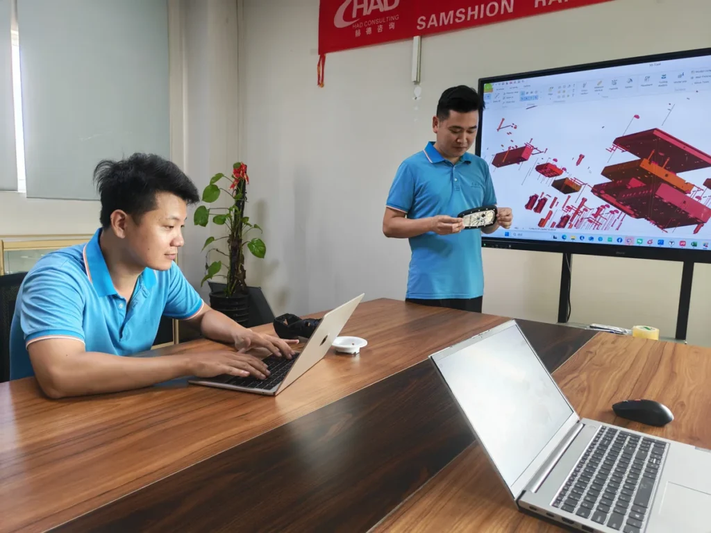
Before mold manufacture, SAMSHION reviews the part for design for manufacturability (DFM). The review identifies molding risks, proposed tooling features and areas that may need adjustment. Recommendations affecting part geometry are submitted for customer approval.
Parting Line, Opening Direction and Undercuts
Review the mold opening direction and parting-line position against the part’s functional and visible surfaces. Identify undercuts that may require slides, lifters, removable inserts or a design adjustment, and explain their effect on tooling complexity and part release.
Draft and Ejection
Check draft angles against feature depth, resin and surface texture. Plan ejector locations and support around ribs, bosses and thin sections to reduce sticking, distortion and unwanted ejector marks.
Wall Thickness, Ribs and Bosses
Review wall transitions, rib proportions and boss connections for local thick sections. Proposed adjustments aim to reduce sink marks, uneven cooling and warpage while retaining the stiffness and assembly features the part requires.
Gates, Runners and Venting
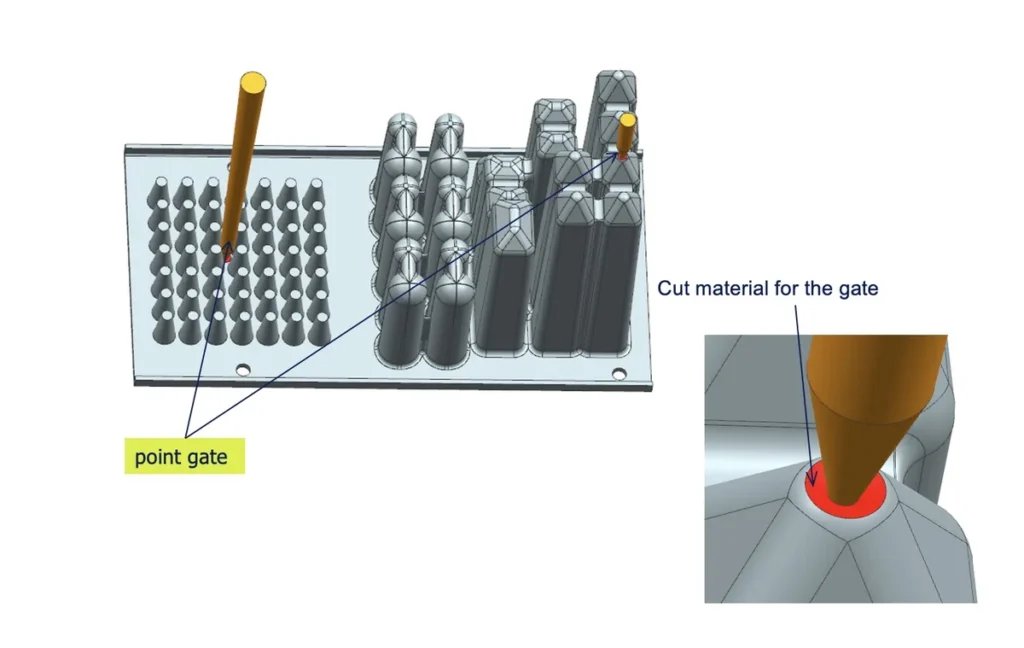
Review gate position, runner layout and air escape paths for filling, packing and visible gate marks. Consider weld-line locations and critical appearance zones before confirming the layout. Our injection molding gate design guide explains these decisions in more detail.
Cooling and Thermal Balance
Assess cooling access around thick sections, deep cores and inserts. The cooling layout should manage local hot spots and support dimensional stability within the proposed mold construction and intended molding cycle.
Steel-Safe Planning for Design Changes
Identify dimensions likely to change after initial samples. Where practical, leave controlled machining allowance so corrections can be made by removing mold material. Changes requiring material addition or replacement inserts are reviewed separately for feasibility, cost and timing.
Surface Finish and Cosmetic Zones
Identify visible surfaces, texture or polish references, and acceptable parting-line, gate and ejector marks. Review these requirements together with draft and tooling access. Additional options are described in our surface finishing services.
Rapid Tooling vs. Other Manufacturing Options
Compare 3D printing, vacuum casting, rapid tooling and production tooling according to the parts you need now and the next stage of your project.
3D Printing
Choose 3D printing services when the design is changing frequently, only a few prototypes are needed, or complex geometry benefits from an additive process. It supports shape, fit and selected functional checks without an injection mold. Printed properties depend on the material, process and build orientation.
Vacuum Casting
Choose vacuum casting services for small batches of polyurethane parts reproduced from a master pattern. This route suits appearance reviews, assembly trials and selected functional evaluations. Cast polyurethane can approximate certain plastic properties, but it is not the specified injection-molding thermoplastic.
Rapid Tooling
Choose rapid tooling when samples or small batches must be injection molded in the intended thermoplastic. It supports prototype validation, pilot builds, bridge supply and repeat low-volume orders. Mold manufacture and potential design changes should be included in the project’s cost and schedule.
Production Tooling
Choose production mold making when stable designs and sustained demand justify investment in long-term molding capacity. The tooling can be developed around cycle efficiency, maintenance access, required output and automation where appropriate. Initial investment and future modification costs need to be assessed against expected demand.
For a project-specific comparison, contact our engineering team with your CAD files, material requirements, expected quantities and intended use.
From Quote to Molded Parts
From CAD review and tooling approval to sample checks, production and repeat orders.
Send CAD Files and Requirements
Share your 3D model, drawing, resin, quantity and target delivery date, together with critical dimensions and finish requirements.
Confirm DFM and Quotation
Review SAMSHION’s DFM feedback, tooling proposal, inspection scope and schedule, then approve the quotation and mold design before manufacture.
Manufacture and Assemble the Mold
SAMSHION machines the mold components, completes EDM where required, and fits and assembles the tool for trial molding.
Review T1 Samples and Corrections
T1 parts are molded and inspected against the agreed requirements. Findings are reviewed, and approved corrections are checked through further sampling where needed.
Approve Samples and Receive Parts
After the agreed sample approval, SAMSHION molds, inspects and packs the production batch for delivery.
Repeat Orders and Tool Maintenance
Repeat orders follow the approved revision, with mold condition and maintenance needs reviewed before the next production run.
Send your current part files and tell us what the molded parts need to achieve. Our team will review the tooling route and next steps.
Rapid Tooling Cost: What Your Budget Should Include
A rapid tooling budget covers both the mold and the parts it will produce. Compare quotations using the same sampling, production, inspection and delivery scope, with allowances for design changes and repeat orders.
Tooling Cost and Part Pricing
Review tooling charges separately from part prices. Confirm what is included in mold manufacture, T1 sampling and inspection, then check batch setup, unit prices, secondary operations and shipping terms. Clear inclusions make quotations easier to compare.
First Batch and Repeat Quantities
Compare the initial sample or pilot order with likely repeat-order quantities. Batch size, cavity count and cycle time influence part cost. Evaluate whether the proposed tool remains economical if demand grows or production is divided into smaller orders.
Design Changes and Additional Trials
Allow for possible design revisions, additional samples and repeat inspection. Confirm how customer-requested changes are quoted and approved, and distinguish these from corrections covered by the original tooling scope.
Total Cost per Accepted Part
Compare the cost of parts that meet your requirements, including agreed inspection, finishing, packaging and delivery. For repeat supply, also account for mold maintenance, storage and replacement, with responsibilities defined in the project terms.
For a project-specific cost breakdown, request a rapid tooling quotation with your CAD files, resin requirements, first-order quantity and expected repeat demand.
Rapid Tooling Tolerances and Inspection
Agree the inspection scope before tooling begins, so molded samples can be assessed against clear dimensional and appearance requirements.
Tolerances Defined by Your Drawing
Identify the dimensions that control fit, assembly and function on your drawing. We review these requirements before mold manufacture and agree on datums and measurement conditions. Tolerances are assessed feature by feature rather than applied as one blanket value.
Dimensional and Visual Inspection
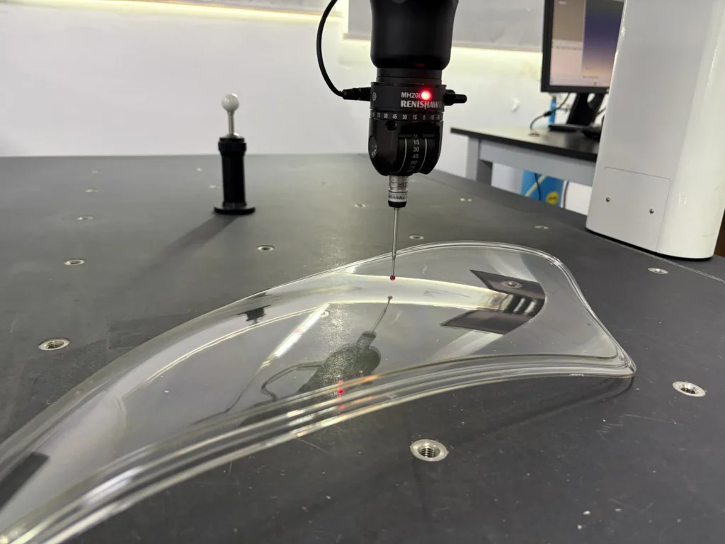
CMM inspection is available for suitable features, alongside other measurement methods selected for the part. The inspection plan defines the dimensions, sample quantity and cosmetic areas to check. Any assembly or functional testing should be agreed separately.
Reports Matched to Your Project
SAMSHION can provide CMM inspection reports, material documentation and T1 inspection information according to the agreed scope. Please specify required report formats, sampling requirements and any additional testing during quotation so they can be included in the project plan.
Explore our quality assurance and inspection capabilities for more information.
Frequently Asked Questions
Is Rapid Tooling Always Made from Aluminum?
No. Rapid tooling describes the purpose of the mold, not one mandatory mold material. SAMSHION offers aluminum, prehardened steel and hybrid construction, selected for the project’s molding and production needs.
How Long Does Rapid Tooling Take?
T1 samples are available from 15 business days after mold design approval, subject to project review. This refers to initial trial samples, not approved production parts or delivery to your facility. We confirm the schedule for tooling, sampling and any required revisions during quotation.
How Many Parts Can a Rapid Mold Produce?
There is no single tool-life figure for every rapid mold. We assess the target production quantity against the proposed tool construction and molding requirements. Share both your first order and expected repeat demand so the quotation can address tool life and maintenance assumptions.
Can Rapid Tooling Produce End-Use Parts?
Yes. Rapid tooling can supply end-use injection-molded parts for pilot orders, bridge production and repeat low-volume runs. Suitability depends on meeting the specified material, dimensional, appearance and functional requirements, plus any application-specific qualification.
Can We Change the Design After T1?
In many cases, yes. We review proposed changes before modifying the mold. A local insert modification may be feasible, while larger geometry changes can require new components or a new mold. The scope, cost and revised sample schedule are agreed before work starts.
Does a Rapid Mold Reproduce the Final Production Process Exactly?
Not necessarily. A rapid mold may use a different cavity layout, gate or cooling arrangement from the later production tool. Its samples can support development, but results that depend on those differences may need to be checked again on the final production setup.
What Files Should I Submit for a Quote?
Submit a 3D CAD model, preferably STEP, and the latest 2D drawing showing critical tolerances and notes. Include the resin grade, color, order quantity, expected repeat demand and target delivery date. You can upload your CAD files and requirements for a quote.
Who Owns the Mold, and What Happens After the First Order?
The customer owns the mold after full payment of the tooling fees. It can be retained for repeat orders or collected or transferred under the agreed project terms. Storage duration, maintenance responsibilities and any related charges should be confirmed in the quotation or purchase agreement.
Start Your Rapid Tooling Project
Upload your 3D CAD model and share the requirements that matter to your program. SAMSHION will review the part, resin, expected demand and validation objective before recommending a tooling route.